Ford Fiesta: Supplemental Restraint System / Front Impact Severity Sensor. Removal and Installation
Removal
 WARNING:
The following procedure prescribes critical repair steps
required for correct restraint system operation during a crash. Follow
all notes and steps carefully. Failure to follow step instructions may
result in incorrect operation of the restraint system and increases the
risk of serious personal injury or death in a crash.
WARNING:
The following procedure prescribes critical repair steps
required for correct restraint system operation during a crash. Follow
all notes and steps carefully. Failure to follow step instructions may
result in incorrect operation of the restraint system and increases the
risk of serious personal injury or death in a crash.
NOTE: Removal steps in this procedure may contain installation details.
-
Depower the SRS .
Refer to: Supplemental Restraint System (SRS) Depowering and Repowering (501-20B Supplemental Restraint System, General Procedures).
-
Remove the front bumper cover.
Refer to: Front Bumper Cover (501-19 Bumpers, Removal and Installation).
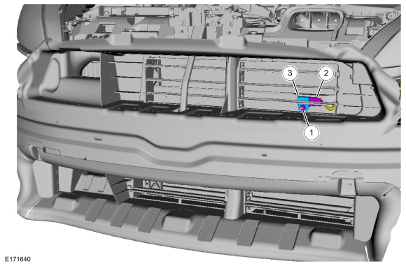
LH sensor
-
NOTE: With active grill shutter shown, without similar.
-
Remove the nut.
Torque: 93 lb.in (10.5 Nm)
-
Disconnect the electrical connector.
-
Remove the front impact severity sensor.
-
Remove the nut.
 |
RH sensor with active grill shutter
-
Position aside the RH side air deflector.
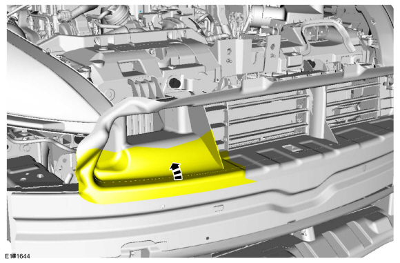 |
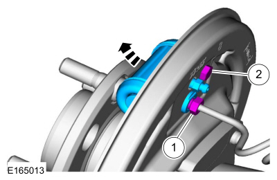
RH sensor
-
NOTE: Active grill shutter panel is removed for clarity.
-
Remove the nut.
Torque: 93 lb.in (10.5 Nm)
-
Disconnect the electrical connector.
-
Remove the front impact severity sensor.
-
Remove the nut.
 |
Installation
-
NOTE: Make sure the front impact severity sensor mating surfaces are clean and free of foreign material.
To install, reverse the removal procedure.
-
Repower the SRS .
Refer to: Supplemental Restraint System (SRS) Depowering and Repowering (501-20B Supplemental Restraint System, General Procedures).
 Front Door Side Impact Sensor. Removal and Installation
Removal
WARNING:
The following procedure prescribes critical repair steps
required for correct restraint system operation during a crash...
 Driver Knee Airbag. Removal and Installation
Special Tool(s) /
General Equipment
Interior Trim Remover
Removal
WARNING:
The following procedure prescribes critical repair steps
required for correct restraint system operation during a crash...
Other information:
Ford Fiesta 2014 - 2019 Service Manual: Stoplamp Switch. Removal and Installation
Removal NOTE: Removal steps in this procedure may contain installation details. NOTICE: Do not press, pull or otherwise move the brake pedal while installing the stoplamp switch and cruise control deactivation switch. Install these switches with the booster push rod attached to the brake pedal and with the brake pedal in the at-rest position...
Ford Fiesta 2014 - 2019 Service Manual: Transmission Fluid Level Check. General Procedures
Materials Name Specification Motorcraft® Dual Clutch Transmission FluidXT-11-QDC WSS-M2C200-D2 Check With the vehicle in N , position it on a hoist. Refer to: Jacking and Lifting - Overview (100-02 Jacking and Lifting, Description and Operation)...
Categories
- Manuals Home
- Ford Fiesta Service Manual (2014 - 2019)
- Front Strut and Spring Assembly. Removal and Installation
- Engine
- Engine Component View. Description and Operation
- Lower Arm. Removal and Installation
- Engine System - General Information
Brake Backing Plate. Removal and Installation
Removal
NOTE: Removal steps in this procedure may contain installation details.
Remove the brake shoes.Refer to: Brake Shoes (206-02 Drum Brake, Removal and Installation).
Disconnect the brake tube fitting.
Torque: 159 lb.in (18 Nm) Remove the bolt and wheel cylinder.
Torque: 106 lb.in (12 Nm)
 Disconnect the brake shoe lever fitting and re