Ford Fiesta: Front End Sheet Metal Repairs / Fender Apron Panel Reinforcement. Removal and Installation
Ford Fiesta 2014 - 2019 Service Manual / Body and Paint / Front End Sheet Metal Repairs / Fender Apron Panel Reinforcement. Removal and Installation
Special Tool(s) / General Equipment
| Resistance Spotwelding Equipment | |
| Grinder | |
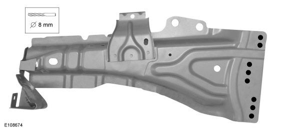
| 8 mm Drill Bit | |
| MIG/MAG Welding Equipment | |
| Spot Weld Drill Bit |
Removal
-
Refer to: Body Repair Health and Safety and General Precautions (100-00 General Information, Description and Operation). WARNING:
Before beginning any service procedure in this
section, refer to Safety Warnings in section 100-00 General Information.
Failure to follow this instruction may result in serious personal
injury.
WARNING:
Before beginning any service procedure in this
section, refer to Safety Warnings in section 100-00 General Information.
Failure to follow this instruction may result in serious personal
injury.
-
Remove the hood.
-
Remove the fender.
Refer to: Fender (501-02 Front End Body Panels, Removal and Installation).
-
Remove the front bumper.
Refer to: Front Bumper (501-19 Bumpers, Removal and Installation).
-
Remove the A-pillar trim panel.
Refer to: A-Pillar Trim Panel (501-05 Interior Trim and Ornamentation, Removal and Installation).
-
Remove the front door.
Refer to: Front Door (501-03 Body Closures, Removal and Installation).
-
Rough straighten to dimensionally restore the vehicle to a pre-accident condition.
Refer to: Body and Frame (501-26 Body Repairs - Vehicle Specific Information and Tolerance Checks, Description and Operation).
-
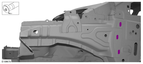
Grind welds at rear flange of the apron reinforcement panel.
Use the General Equipment: Grinder
 |
-
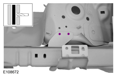
Drill out the spot welds.
Use the General Equipment: Spot Weld Drill Bit
 |
-
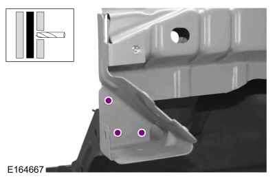
Drill out the spot welds.
Use the General Equipment: Spot Weld Drill Bit
 |
-
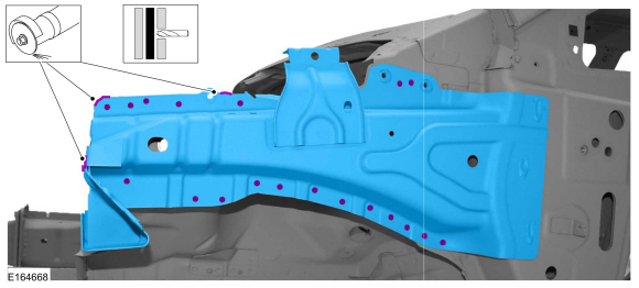
Remove the welds and remove the fender apron panel reinforcement.
Use the General Equipment: Spot Weld Drill Bit
Use the General Equipment: Grinder
 |
Installation
-
NOTE: If the factory-installed MIG brazed joints are replaced by MIG plug welds, plug welds must be placed in a different position.
NOTE: These MIG welds must not be carried out on or in the immediate vicinity of existing MIG brazed seams as even the smallest amount of brazing solder can result in a reduction in strength of the weld seam.
Drill plug welds holes in replacement panel.
Use the General Equipment: 8 mm Drill Bit
 |
-
Assure correct placement of all components.
Refer to: Body and Frame (501-26 Body Repairs - Vehicle Specific Information and Tolerance Checks, Description and Operation).
-
Install the fender apron panel reinforcement and install welds.
Use the General Equipment: Resistance Spotwelding Equipment
Use the General Equipment: MIG/MAG Welding Equipment
 |
-
Install plug welds.
Use the General Equipment: MIG/MAG Welding Equipment
 |
-
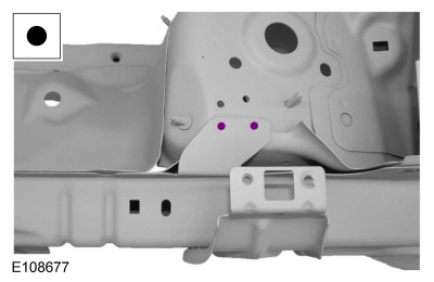
Install spot welds.
Use the General Equipment: Resistance Spotwelding Equipment
 |
-
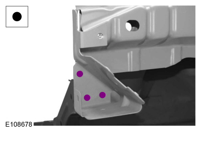
Install spot welds.
Use the General Equipment: Resistance Spotwelding Equipment
 |
-
Refinish using a Ford approved paint system and typical refinishing techniques.
-
Restore corrosion protection.
Refer to: Corrosion Prevention (501-25 Body Repairs - General Information, General Procedures).
-
Install the A-pillar trim panel.
Refer to: A-Pillar Trim Panel (501-05 Interior Trim and Ornamentation, Removal and Installation).
-
Install the front door.
Refer to: Front Door (501-03 Body Closures, Removal and Installation).
-
Install the fender.
Refer to: Fender (501-02 Front End Body Panels, Removal and Installation).
-
Install the following items.
Refer to: Front Bumper (501-19 Bumpers, Removal and Installation).
Refer to: Front Bumper Cover (501-19 Bumpers, Removal and Installation).
-
Install and align the hood.
-
Install the following items.
Refer to: Headlamp Assembly (417-01 Exterior Lighting, Removal and Installation).
Refer to: Front Fog Lamp (417-01 Exterior Lighting, Removal and Installation).

 Front Side Member and Fender Apron Panel LH. Removal and Installation
Special Tool(s) /
General Equipment
Resistance Spotwelding Equipment
Grinder
8 mm Drill Bit
MIG/MAG Welding Equipment
Spot Weld Drill Bit
Removal
WARNING:
Before beginning any service procedure in this
section, refer to Safety Warnings in section 100-00 General Information...
Other information:
Ford Fiesta 2014 - 2019 Service Manual: Battery Cables. Removal and Installation
Removal Negative battery cable If equipped, remove the battery monitoring sensor. Refer to: Battery Monitoring Sensor (414-01 Battery, Mounting and Cables, Removal and Installation). Remove the nut...
Ford Fiesta 2014 - 2019 Service Manual: Evaporative Emission Canister. Removal and Installation
Removal NOTE: Removal steps in this procedure may contain installation details. With the vehicle in NEUTRAL, position it on a hoist. Refer to: Jacking and Lifting - Overview (100-02 Jacking and Lifting, Description and Operation)...
Categories
- Manuals Home
- Ford Fiesta Service Manual (2014 - 2019)
- Camshafts. Removal and Installation
- Fuel Pump. Removal and Installation
- Timing Belt. Removal and Installation
- Manual Transmission - 6-Speed Manual Transmission – B6
- Lower Arm. Removal and Installation
Rear Wheel Speed Sensor. Removal and Installation
Removal
NOTE: Removal steps in this procedure may contain installation details.
Remove the retainer and pull the rear splash shield outward.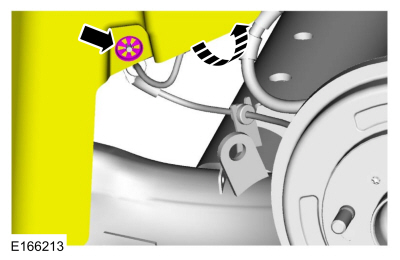 Disconnect the electrical connector and detach the wiring retainer.
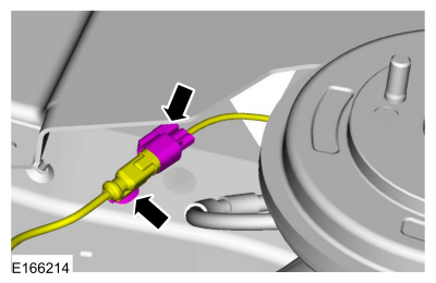
Copyright © 2026 www.fofiesta7.com