Ford Fiesta: Exterior Lighting / Reversing Lamps. Diagnosis and Testing
Diagnostics in this manual assume a certain skill level and knowledge of Ford-specific diagnostic practices.
REFER to: Diagnostic Methods (100-00 General Information, Description and Operation).
DTC Chart: BCM
BCM
DTC Chart
|
BCM
|
Description
|
Action
|
|
C1137:24
|
Reverse Gear Switch: Signal Stuck High
|
GO to Pinpoint Test C
|
Symptom Chart(s)
Diagnostics in this manual assume a certain skill level and knowledge of Ford-specific diagnostic practices.
REFER to: Diagnostic Methods (100-00 General Information, Description and Operation).
Symptom Chart: Reversing Lamps
Symptom Chart
|
Condition
|
Possible Sources
|
Actions
|
|
A module does not respond to the diagnostic scan tool
|
-
Fuse
-
Wiring, terminals or connectors
-
Module
|
REFER to: Communications Network (418-00 Module Communications Network, Diagnosis and Testing).
|
|
All the reversing lamps are inoperative
|
Refer to the Pinpoint Test
|
GO to Pinpoint Test A
|
|
An individual reversing lamp is inoperative
|
Refer to the Pinpoint Test
|
GO to Pinpoint Test B
|
|
The reversing lamps are on continuously
|
Refer to the Pinpoint Test
|
GO to Pinpoint Test C
|
Pinpoint Tests
All the Reversing Lamps Are Inoperative
Refer to Wiring Diagrams Cell 93 for schematic and connector information.
Normal Operation and Fault Conditions
REFER to: Exterior Lighting - System Operation and Component Description (417-01 Exterior Lighting, Description and Operation).
Possible Sources
-
Fuse
-
Wiring, terminals or connectors
-
Reversing lamp switch (manual transmission)
-
Reversing lamps relay (automatic transmission)
-
TCM (automatic transmission)
Visual Inspection and Diagnostic Pre-checks
-
Inspect CJB fuse 6 (10A).
PINPOINT TEST A: ALL THE REVERSING LAMPS ARE INOPERATIVE
| A1 DETERMINE THE TRANSMISSION TYPE |
-
Check the vehicle for a manual transmission.
Is the vehicle equipped with a manual transmission?
| Yes |
VERIFY the CJB fuse 6 (10A) is OK. If OK, GO to A2 If not OK, REFER to
the Wiring Diagrams manual to identify the possible causes of the
circuit short.
|
| No |
VERIFY the CJB fuse 6 (10A) is OK. If OK, GO to A4If not OK, REFER to
the Wiring Diagrams manual to identify the possible causes of the
circuit short.
|
|
| A2 CHECK FOR VOLTAGE TO THE REVERSING LAMP SWITCH |
-
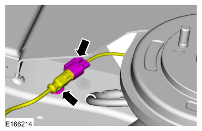
Disconnect: Reversing Lamp Switch C1131.
-
Measure:
Click to display connectors
|
Positive Lead
|
Measurement / Action
|
Negative Lead
|
|
C1131-1
|

|
Ground
|
Is the voltage greater than 11 volts?
|
| A3 BYPASS THE REVERSING LAMP SWITCH |
-
Connect a fused jumper wire:
Click to display connectors
|
Positive Lead
|
Measurement / Action
|
Negative Lead
|
|
C1131-1
|

|
C1131-2
|
Do the reversing lamps illuminate?
| Yes |
REMOVE the fused jumper wire. INSTALL a new reversing lamp switch.
REFER to: Reversing Lamp Switch (417-01 Exterior Lighting, Removal and Installation).
|
| No |
For 4-door vehicles, REMOVE the fused jumper wire. GO to A9
For 5-door vehicles, REMOVE the fused jumper wire. REPAIR the reversing lamps voltage supply circuit.
|
|
| A4 CHECK THE REVERSING LAMPS RELAY |
-
Disconnect: reversing lamps relay.
-
Substitute a known good relay and recheck the reversing lamps operation.
Do the reversing lamps operate correctly?
| Yes |
REMOVE the known good relay. INSTALL a new reversing lamps relay.
|
| No |
REMOVE the known good relay. GO to A5
|
|
| A5 CHECK FOR VOLTAGE TO THE REVERSING LAMPS RELAY |
-
Measure:
Click to display connectors
|
Positive Lead
|
Measurement / Action
|
Negative Lead
|
|
Reversing Lamps Relay Pin 1
|
|
Ground
|
Click to display connectors
|
Positive Lead
|
Measurement / Action
|
Negative Lead
|
|
Reversing Lamps Relay Pin 3
|
|
Ground
|
Are the voltages greater than 10 volts?
| No |
REPAIR the circuit in question.
|
|
| A6 BYPASS THE REVERSING LAMPS RELAY |
-
Connect a fused jumper wire:
Click to display connectors
|
Positive Lead
|
Measurement / Action
|
Negative Lead
|
|
Reversing Lamps Relay Pin 3
|
|
Reversing Lamps Relay Pin 5
|
Do the reversing lamps illuminate?
| Yes |
REMOVE the fused jumper wire. GO to A7
|
| No |
For 4-door vehicles, REMOVE the fused jumper wire. GO to A9
For 5-door vehicles, REMOVE the fused jumper wire. REPAIR the reversing lamps voltage supply circuit.
|
|
| A7 CHECK THE REVERSING LAMPS RELAY CONTROL CIRCUIT FOR A SHORT TO VOLTAGE |
-
Measure:
Click to display connectors
|
Positive Lead
|
Measurement / Action
|
Negative Lead
|
|
Reversing Lamps Relay Pin 2
|
|
Ground
|
Is any voltage present?
|
| A8 CHECK THE REVERSING LAMPS RELAY CONTROL CIRCUIT FOR AN OPEN |
-
Measure:
Click to display connectors
|
Positive Lead
|
Measurement / Action
|
Negative Lead
|
|
Reversing Lamps Relay Pin 2
|

|
C1750A-40
|
Is the resistance less than 3 ohms?
|
| A9 CHECK THE REVERSING LAMPS GROUND CIRCUIT FOR AN OPEN |
-
Disconnect: LH Reversing Lamp C498.
-
Measure:
Click to display connectors
|
Positive Lead
|
Measurement / Action
|
Negative Lead
|
|
C498-1
|
|
C498-4
|
Is the resistance less than 3 ohms?
| Yes |
REPAIR the reversing lamps voltage supply circuit.
|
|
| A10 CHECK FOR CORRECT BCM (BODY CONTROL MODULE)
OPERATION |
-
Disconnect and inspect all BCM connectors.
-
Repair:
-
corrosion (install new connector or terminals – clean module pins)
-
damaged or bent pins – install new terminals/pins
-
pushed-out pins – install new pins as necessary
-
Reconnect the BCM connectors. Make sure they seat and latch correctly.
-
Operate the system and determine if the concern is still present.
Is the concern still present?
| Yes |
CHECK OASIS for any applicable Technical Service Bulletins (TSBs). If a
TSB exists for this concern, DISCONTINUE this test and FOLLOW TSB
instructions. If no Technical Service Bulletins (TSBs) address this
concern, INSTALL a new BCM .
REFER to: Body Control Module (BCM) (419-10 Multifunction Electronic Modules, Removal and Installation).
|
| No |
The system is operating correctly at this time. The
concern may have been caused by module connections. ADDRESS the root
cause of any connector or pin issues.
|
|
An Individual Reversing Lamp Is Inoperative
Refer to Wiring Diagrams Cell 93 for schematic and connector information.
Normal Operation and Fault Conditions
REFER to: Exterior Lighting - System Operation and Component Description (417-01 Exterior Lighting, Description and Operation).
Possible Sources
-
Bulb
-
Wiring, terminals or connectors
PINPOINT TEST B: AN INDIVIDUAL REVERSING LAMP IS INOPERATIVE
| B1 CHECK FOR VOLTAGE TO THE REVERSING LAMP |
-
Disconnect: Inoperative 4-Door LH Reversing Lamp C498 or RH Reversing Lamp C499.
-
Disconnect: Inoperative 5-Door LH Rear Lamp C414 or RH Rear Lamp C417.
-
Place the gear selector lever in the reverse.
-
Measure:
Click to display connectors
4-Door LH Reversing Lamp
|
Positive Lead
|
Measurement / Action
|
Negative Lead
|
|
C498-1
|
|
Ground
|
Click to display connectors
4-Door RH Reversing Lamp
|
Positive Lead
|
Measurement / Action
|
Negative Lead
|
|
C499-1
|
|
Ground
|
Click to display connectors
5-Door LH Rear Lamp
|
Positive Lead
|
Measurement / Action
|
Negative Lead
|
|
C414-3
|
|
Ground
|
Click to display connectors
5-Door RH Rear Lamp
|
Positive Lead
|
Measurement / Action
|
Negative Lead
|
|
C417-3
|
|
Ground
|
Is the voltage greater than 11 volts?
| No |
REPAIR the reversing lamp voltage supply circuit.
|
|
| B2 CHECK THE REVERSING LAMP GROUND CIRCUIT FOR AN OPEN |
-
Measure:
Click to display connectors
4-Door LH Reversing Lamp
|
Positive Lead
|
Measurement / Action
|
Negative Lead
|
|
C498-1
|
|
C498-4
|
Click to display connectors
4-Door RH Reversing Lamp
|
Positive Lead
|
Measurement / Action
|
Negative Lead
|
|
C499-1
|
|
C499-4
|
Click to display connectors
5-Door LH Rear Lamp
|
Positive Lead
|
Measurement / Action
|
Negative Lead
|
|
C414-3
|
|
C414-6
|
Click to display connectors
5-Door RH Rear Lamp
|
Positive Lead
|
Measurement / Action
|
Negative Lead
|
|
C417-3
|
|
C417-6
|
Is the voltage greater than 11 volts?
| Yes |
For 4-door vehicles, INSTALL a new bulb.
For 5-door vehicles, VERIFY the bulb is OK. If OK,
REPAIR or INSTALL a new rear lamp jumper harness. If not OK, INSTALL a
new bulb.
|
|
The Reversing Lamps Are On Continuously
Refer to Wiring Diagrams Cell 93 for schematic and connector information.
Normal Operation and Fault Conditions
REFER to: Exterior Lighting - System Operation and Component Description (417-01 Exterior Lighting, Description and Operation).
DTC Fault Trigger Conditions
|
DTC
|
Description
|
Fault Trigger Conditions
|
|
C1137:24
|
Reverse Gear Switch: Signal Stuck High
|
A continuous and on-demand DTC that sets when the BCM detects one of the following:
-
Reversing lamp switch input detects
voltage (transmission selector in REVERSE) for greater than 1 second
while the vehicle speed is greater than 60 km/h (37 mph).
-
Reversing lamp switch input detects a short to ground during the BCM self-test.
|
Possible Sources
-
Wiring, terminals or connectors
-
Gear range input
-
GPSM
-
TCM
-
Auto-dimming interior rear view mirror
-
BCM
PINPOINT TEST C: THE REVERSING LAMPS ARE ON CONTINUOUSLY
| C1 DETERMINE THE TRANSMISSION TYPE |
-
Check the vehicle for a manual transmission.
Is the vehicle equipped with a manual transmission?
|
| C2 CHECK THE REVERSING LAMP SWITCH |
-
Disconnect: Reversing Lamp Switch C1131.
Do the reversing lamps continue to illuminate?
| Yes |
If equipped with SYNC®, GO to C4
If not equipped with SYNC®, GO to C5
|
| No |
INSTALL a new reversing lamp switch.
REFER to: Reversing Lamp Switch (417-01 Exterior Lighting, Removal and Installation).
|
|
| C3 CHECK THE REVERSING LAMPS RELAY OUTPUT |
-
Disconnect: reversing lamps relay.
Do the reversing lamps continue to illuminate?
| Yes |
If equipped with SYNC®, GO to C4
If not equipped with SYNC®, GO to C5
|
|
| C4 CHECK THE GPSM (GLOBAL POSITIONING SYSTEM MODULE)
FOR A SHORT TO VOLTAGE |
Do the reversing lamps continue to illuminate?
|
| C5 CHECK THE BCM (BODY CONTROL MODULE)
FOR A SHORT TO VOLTAGE |
Do the reversing lamps continue to illuminate?
| Yes |
If equipped with an auto-dimming interior rear view mirror, GO to C6
If not equipped with an auto-dimming interior rear
view mirror, REPAIR the reversing lamps voltage supply circuit for a
short to voltage.
|
|
| C6 CHECK THE AUTO-DIMMING INTERIOR REAR VIEW MIRROR FOR A SHORT TO VOLTAGE |
-
Disconnect: Auto-Dimming Interior Rear View Mirror C911 (without rain sensor).
-
Disconnect: Auto-Dimming Interior Rear View Mirror C9012 (with rain sensor).
Do the reversing lamps continue to illuminate?
| No |
INSTALL a new auto-dimming interior rear view mirror.
REFER to: Interior Rear View Mirror (501-09 Rear View Mirrors, Removal and Installation).
|
|
| C7 CHECK THE REVERSING LAMPS RELAY |
-
Disconnect: reversing lamps relay.
-
Substitute a known good relay.
Do the reversing lamps continue to illuminate?
| Yes |
REMOVE the known good relay. GO to C8
|
| No |
REMOVE the known good relay. INSTALL a new reversing lamps relay.
|
|
| C8 CHECK THE REVERSING LAMPS RELAY ENABLE CIRCUIT FOR A SHORT TO GROUND |
-
Connect: reversing lamps relay.
Do the reversing lamps continue to illuminate?
|
| C9 CHECK THE TCM (TRANSMISSION CONTROL MODULE)
GEAR STATUS INPUT PID (PARAMETER IDENTIFICATION)
|
-
Using a diagnostic scan tool, view TCM Parameter Identifications (PIDs).
-
Monitor the TCM GEAR_ENGAGED PID while placing the gear selector lever through all its positions.
Does the PID agree with the gear selections?
| No |
REFER to: Automatic Transmission (307-01 Automatic Transmission -
6-Speed PowerShift Transmission – DPS6/6DCT250, Diagnosis and Testing).
to diagnose the gear input.
|
|
| C10 CHECK FOR CORRECT GPSM (GLOBAL POSITIONING SYSTEM MODULE)
OPERATION |
-
Disconnect and inspect the GPSM connector.
-
Repair:
-
corrosion (install new connector or terminals – clean module pins)
-
damaged or bent pins – install new terminals/pins
-
pushed-out pins – install new pins as necessary
-
Reconnect the GPSM connector. Make sure it seats and latches correctly.
-
Operate the system and determine if the concern is still present.
Is the concern still present?
| Yes |
CHECK OASIS for any applicable Technical Service Bulletins (TSBs). If a
TSB exists for this concern, DISCONTINUE this test and FOLLOW TSB
instructions. If no Technical Service Bulletins (TSBs) address this
concern, INSTALL a new GPSM . For vehicles not equipped with a
touchscreen,
REFER to: Global Positioning System Module (GPSM)
(415-00A Information and Entertainment System - General Information -
Vehicles With: AM/FM/CD/SYNC, Removal and Installation).
For vehicles equipped with a touchscreen,
|
| No |
The system is operating correctly at this time. The
concern may have been caused by module connections. ADDRESS the root
cause of any connector or pin issues.
|
|
| C11 CHECK FOR CORRECT BCM (BODY CONTROL MODULE)
OPERATION |
-
Disconnect and inspect all BCM connectors.
-
Repair:
-
corrosion (install new connector or terminals – clean module pins)
-
damaged or bent pins – install new terminals/pins
-
pushed-out pins – install new pins as necessary
-
Reconnect the BCM connectors. Make sure they seat and latch correctly.
-
Operate the system and determine if the concern is still present.
Is the concern still present?
| Yes |
CHECK OASIS for any applicable Technical Service Bulletins (TSBs). If a
TSB exists for this concern, DISCONTINUE this test and FOLLOW TSB
instructions. If no Technical Service Bulletins (TSBs) address this
concern, INSTALL a new BCM .
REFER to: Body Control Module (BCM) (419-10 Multifunction Electronic Modules, Removal and Installation).
|
| No |
The system is operating correctly at this time. The
concern may have been caused by module connections. ADDRESS the root
cause of any connector or pin issues.
|
|
| C12 CHECK FOR CORRECT TCM (TRANSMISSION CONTROL MODULE)
OPERATION |
-
Disconnect and inspect all TCM connectors.
-
Repair:
-
corrosion (install new connector or terminals – clean module pins)
-
damaged or bent pins – install new terminals/pins
-
pushed-out pins – install new pins as necessary
-
Reconnect the TCM connectors. Make sure they seat and latch correctly.
-
Operate the system and determine if the concern is still present.
Is the concern still present?
| Yes |
CHECK OASIS for any applicable Technical Service Bulletins (TSBs). If a
TSB exists for this concern, DISCONTINUE this test and FOLLOW TSB
instructions. If no Technical Service Bulletins (TSBs) address this
concern, INSTALL a new TCM .
REFER to: Transmission Control Module
(TCM) (307-01 Automatic Transmission - 6-Speed PowerShift Transmission –
DPS6/6DCT250, Removal and Installation).
|
| No |
The system is operating correctly at this time. The
concern may have been caused by module connections. ADDRESS the root
cause of any connector or pin issues.
|
|
Diagnostics in this manual assume a certain skill level and knowledge of Ford-specific diagnostic practices. REFER to: Diagnostic Methods (100-00 General Information, Description and Operation)...
Diagnostics in this manual assume a certain skill level and knowledge of Ford-specific diagnostic practices. REFER to: Diagnostic Methods (100-00 General Information, Description and Operation)...
Other information:
Materials
Name
Specification
Motorcraft® Ultra-Clear Spray Glass CleanerZC-23
ESR-M14P5-A
Motorcraft® Rear Window Defroster RepairPM-11
WSB-M4J58-B
Motorcraft® Lacquer Touch-Up PaintPMPC-19500-XXXXA, PMPM-19500-XXXXG, PMPP-19500-XXXXA
ESR-M2P100-C
Repair
NOTE:
The antenna and heated window grid line material is not..
Removal
NOTE:
Removal steps in this procedure may contain installation details.
Remove the instrument panel center upper trim panel.
Refer to: Instrument Panel Center Upper Trim Panel (501-12 Instrument Panel and Console, Removal and Installation).
Remove the bolts and the FCDIM .
Disconnect the electrical connector.
Torque:
11 lb.in (1..
 Parking, Rear and License Plate Lamps. Diagnosis and Testing
 Stoplamps. Diagnosis and Testing
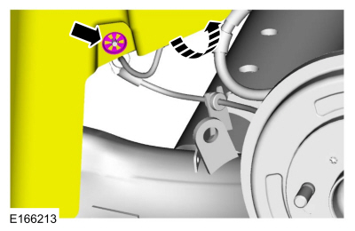 Disconnect the electrical connector and detach the wiring retainer.