
Ford Fiesta: Evaporative Emissions - 1.6L EcoBoost (132kW/180PS) – Sigma / Evaporative Emissions - System Operation and Component Description. Description and Operation
Ford Fiesta 2014 - 2019 Service Manual / Engine / Evaporative Emissions - 1.6L EcoBoost (132kW/180PS) – Sigma / Evaporative Emissions - System Operation and Component Description. Description and Operation
System Operation
Refer to the PC/ED manual section 1 Description and Operation.
System Diagram
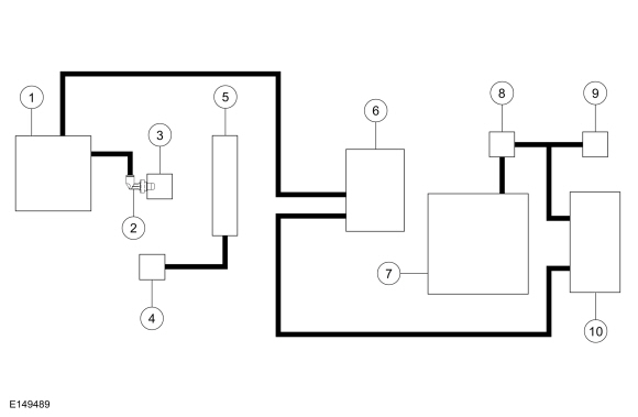
| Item | Service Part Number | Description |
|---|---|---|
| 1 | 9424 | Intake manifold |
| 2 | - | PCV valve (part of 6A785) |
| 3 | 6A785 | Crankcase vent oil separator |
| 4 | 9E652 | Air Cleaner (ACL) outlet pipe |
| 5 | 6582 | Valve cover |
| 6 | 9D289 | EVAP canister purge valve |
| 7 | 9002 | Fuel tank |
| 8 | - | Fuel Tank Pressure (FTP) sensor and tube (part of 9C047) |
| 9 | 9034 | Fuel tank filler pipe |
| 10 | 9D653 | EVAP canister |
 Evaporative Emissions - Overview. Description and Operation
Overview
The EVAP
system prevents hydrocarbon emissions from entering the atmosphere by
storing fuel vapors and routing the vapors to the engine to be consumed
during normal engine operation...
 Evaporative Emissions. Diagnosis and Testing
Engine Diagnostic Information
Diagnostics
in this manual assume a certain skill level and knowledge of
Ford-specific diagnostic practices. For information about these,REFER to: Diagnostic Methods (100-00 General Information, Description and Operation)...
Other information:
Ford Fiesta 2014 - 2019 Service Manual: Airbag and Seatbelt Pretensioner Supplemental Restraint System (SRS) - System Operation and Component Description. Description and Operation
System Operation System Diagram - Supplemental Restraint System (SRS) Item Description 1 RCM 2 HS-CAN 3 Passenger Front Door Impact Severity Sensor 4 Driver Safety Belt Buckle Sensor 5 RF Passenger Safety Belt Buckle Sensor 6 RH Front Impact Severity Sensor 7 Driver Front Door Impact Severity Sen..
Ford Fiesta 2014 - 2019 Service Manual: Valve Guide Inner Diameter. General Procedures
Check NOTE: Refer to the appropriate Section 303-01 for the specification. NOTE: Valve guides tend to wear in an hourglass pattern. The ball gauge can be inserted into the combustion chamber side of the valve guide, if necessary. Use a ball gauge to determine the inside diameter of the valve guides in 2 directions at the top, middle and bottom of the val..
Categories
- Manuals Home
- Ford Fiesta Service Manual (2014 - 2019)
- Engine System - General Information
- Service Information
- Valve Cover. Removal and Installation
- Engine - 1.6L EcoBoost (132kW/180PS) – Sigma
- Manual Transmission, Clutch, Transfer Case and Power Transfer Unit
Ride Height Measurement. General Procedures
Special Tool(s) / General Equipment
Surface GaugeCheck
Ride Height Measurement - Front
NOTE: Make sure that the vehicle is positioned on a flat, level surface and the tires are inflated to the correct pressure. Vehicle should have a full tank of fuel.
Ride height = 2-3Measurement 2
Measurement 3
Use the General Equipment: Surface Gauge

Copyright © 2026 www.fofiesta7.com