Ford Fiesta: Auxiliary Climate Control / Electric Booster Heater. Removal and Installation
Ford Fiesta 2014 - 2019 Service Manual / Climate Control System / Auxiliary Climate Control / Electric Booster Heater. Removal and Installation
Removal
NOTE: Removal steps in this procedure may contain installation details.
-
Remove the heater core and evaporator core housing - vehicles with:
EMTC and remove the heater core and evaporator core housing - vehicles
with: EATC .
Refer to: Heater Core and Evaporator Core Housing - Vehicles With: Electronic Manual Temperature Control (EMTC) (412-00 Climate Control System - General Information, Removal and Installation).
Refer to: Heater Core and Evaporator Core Housing - Vehicles With: Electronic Automatic Temperature Control (EATC) (412-00 Climate Control System - General Information, Removal and Installation).
-
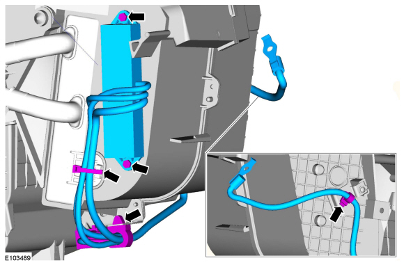
Detach the wiring harness retainers, remove the retainers and the electric heater booster.
 |
Installation
-
To install, reverse the removal procedure.
 Auxiliary Climate Control. Diagnosis and Testing
DTC Chart: Heating, Ventilation And Air Conditioning (HVAC) Control Module
Diagnostics
in this manual assume a certain skill level and knowledge of
Ford-specific diagnostic practices...

Other information:
Ford Fiesta 2014 - 2019 Service Manual: Steering Wheel. Removal and Installation
Special Tool(s) / General Equipment Adhesive Tape Removal NOTE: The removal steps in this procedure may include installation details. Remove the driver airbag. Refer to: Driver Airbag (501-20B Supplemental Restraint System, Removal and Installation). NOTE: Make sure that the road wheels are in the straight ahead position. ..
Ford Fiesta 2014 - 2019 Service Manual: C-Pillar Lower Trim Panel. Removal and Installation
Removal NOTE: RH side shown, LH side similar. NOTE: Removal steps in this procedure may contain installation details. NOTE: To avoid damage to the trim panels, remove any retaining clips from the body and attach them to the trim panels before installing. All vehicles Position aside the rear door weatherstrip. ..
Categories
- Manuals Home
- Ford Fiesta Service Manual (2014 - 2019)
- Fuel Pump. Removal and Installation
- Engine. Assembly
- Manual Transmission, Clutch, Transfer Case and Power Transfer Unit
- Maintenance Schedules
- Engine System - General Information
Ride Height Measurement. General Procedures
Special Tool(s) / General Equipment
Surface GaugeCheck
Ride Height Measurement - Front
NOTE: Make sure that the vehicle is positioned on a flat, level surface and the tires are inflated to the correct pressure. Vehicle should have a full tank of fuel.
Ride height = 2-3Measurement 2
Measurement 3
Use the General Equipment: Surface Gauge
Copyright © 2026 www.fofiesta7.com