Ford Fiesta: Engine System - General Information / Cylinder Head Distortion. General Procedures
Ford Fiesta 2014 - 2019 Service Manual / Engine / Engine System - General Information / Cylinder Head Distortion. General Procedures
Special Tool(s) / General Equipment
| Feeler Gauge |
Check
NOTE: Refer to the appropriate Section 303-01 for the specification.
-
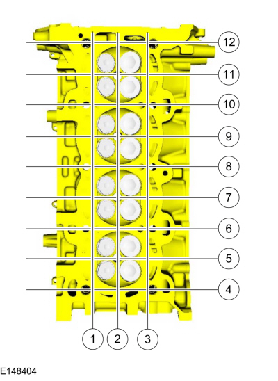
NOTE: Make sure all cylinder head surfaces are clear of any gasket material, silicone sealant, oil and coolant. The cylinder head surface must be clean and dry before running a flatness check.
NOTE: Use a Straightedge that is calibrated by the manufacturer to be flat within 0.005 mm (0.0002 in) per running foot of length, such as Snap-On® GA438A or equivalent. For example, if the Straightedge is 61 cm (24 in) long, the machined edge must be flat within 0.010 mm (0.0004 in) from end to end.
Using a Straightedge and a Feeler Gauge Set, inspect the cylinder head for flatness in the sequence shown.
Use the General Equipment: Feeler Gauge
 |
 Cylinder Bore Taper. General Procedures
Check
NOTE:
Refer to the appropriate Section 303-01 for the specification.
Measure the cylinder bore at the top, middle and bottom
of piston ring travel in 2 directions as indicated...
 Exhaust Manifold Cleaning and Inspection. General Procedures
Special Tool(s) /
General Equipment
Feeler Gauge
Cleaning
Clean the exhaust manifold using a suitable solvent. Use
a plastic scraping tool to clean the gasket sealing surfaces...
Other information:
Ford Fiesta 2014 - 2019 Service Manual: Clutch - System Operation and Component Description. Description and Operation
System Operation How the clutch works Cross-sectional view of a single disc dry clutch Item Description A Clutch disengaged B Clutch engaged 1 Flywheel 2 Clutch disc 3 Pressure plate 4 Diaphragm spring 5 Transmission input shaft 6 Clutch cover 7 Crankshaft The..
Ford Fiesta 2014 - 2019 Service Manual: Pinpoint Test - DTC: H. Diagnosis and Testing
B007E:11, B007E:12, B007E:13 and B007E:1A Refer to Wiring Diagrams Cell 46 for schematic and connector information. Normal Operation and Fault Conditions The RCM continuously monitors the driver safety belt retractor pretensioner circuits for the following faults: Resistance out of range Unexpected voltage Short to ground Faulted driver s..
Categories
- Manuals Home
- Ford Fiesta Service Manual (2014 - 2019)
- Service Information
- Clutch - 6-Speed Manual Transmission – B6
- Engine Component View. Description and Operation
- Jacking and Lifting - Overview. Description and Operation
- Lower Arm. Removal and Installation
Brake Backing Plate. Removal and Installation
Removal
NOTE: Removal steps in this procedure may contain installation details.
Remove the brake shoes.Refer to: Brake Shoes (206-02 Drum Brake, Removal and Installation).
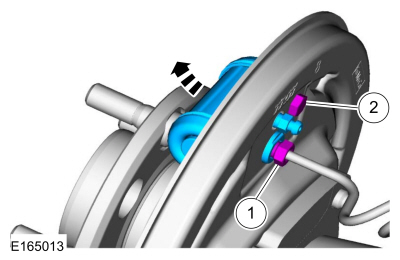
Disconnect the brake tube fitting.
Torque: 159 lb.in (18 Nm) Remove the bolt and wheel cylinder.
Torque: 106 lb.in (12 Nm)
 Disconnect the brake shoe lever fitting and re
Copyright © 2026 www.fofiesta7.com