
Ford Fiesta: Cruise Control / Cruise Control Deactivator Switch. Removal and Installation
Removal
NOTE: Removal steps in this procedure may contain installation details.
-
Refer to: Health and Safety Precautions (100-00 General Information, Description and Operation). WARNING:
Before beginning any service procedure in this
section, refer to Safety Warnings in section 100-00 General Information.
Failure to follow this instruction may result in serious personal
injury.
WARNING:
Before beginning any service procedure in this
section, refer to Safety Warnings in section 100-00 General Information.
Failure to follow this instruction may result in serious personal
injury.
-
NOTICE: Do not press, pull or otherwise move the brake pedal while installing the stoplamp switch and cruise control deactivation switch. Install these switches with the booster push rod attached to the brake pedal and with the brake pedal in the at-rest position. Installing these switches with the brake pedal in any other position results in incorrect adjustment and damages the switches.
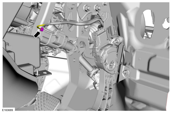
Disconnect the cruise control deactivator switch electrical connector.
 |
-
-
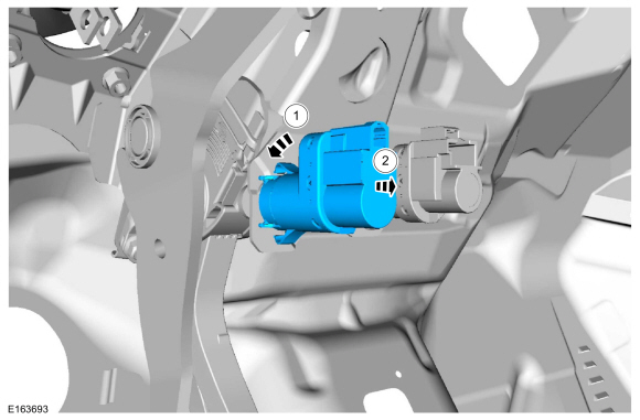
Rotate the cruise control deactivator switch counter clockwise.
-
Remove the cruise control deactivator switch.
-
Rotate the cruise control deactivator switch counter clockwise.
 |
Installation
-
To install, reverse the removal procedure.
 Cruise Control. Diagnosis and Testing
DTC Chart(s):
Diagnostics in this manual assume a certain skill level and knowledge of Ford-specific diagnostic practices. REFER to: Diagnostic Methods (100-00 General Information, Description and Operation)...

Other information:
Ford Fiesta 2014 - 2019 Service Manual: Steering Wheel Cover Repair. General Procedures
Materials Name Specification Motorcraft® Instant Gel AdhesiveTA-19-C WSS-M2G401-B5 Repair NOTE: If re-adhering leather to the front side of the steering wheel only, it will not be necessary to remove the steering wheel. Steering wheel removal is necessary only when repairing loose leather on the backside of the steering wheel. If nece..
Ford Fiesta 2014 - 2019 Service Manual: Safety Precautions - Overview. Description and Operation
Overview WARNING: Before beginning any service procedure in this section, refer to Safety Warnings in section 100-00 General Information. Failure to follow this instruction may result in serious personal injury. Refer to: Health and Safety Precautions (100-00 General Information, Description and Operation). WARNING: Before servicing any tire, ask the ..
Categories
- Manuals Home
- Ford Fiesta Service Manual (2014 - 2019)
- Service Information
- Manual Transmission - 6-Speed Manual Transmission – B6
- Engine Component View. Description and Operation
- Front Suspension
- Engine System - General Information
Brake Backing Plate. Removal and Installation
Removal
NOTE: Removal steps in this procedure may contain installation details.
Remove the brake shoes.Refer to: Brake Shoes (206-02 Drum Brake, Removal and Installation).
Disconnect the brake tube fitting.
Torque: 159 lb.in (18 Nm) Remove the bolt and wheel cylinder.
Torque: 106 lb.in (12 Nm)
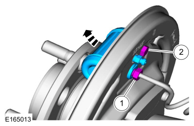 Disconnect the brake shoe lever fitting and re
