Ford Fiesta: Engine - 1.6L EcoBoost (132kW/180PS) – Sigma / Crankshaft Rear Seal. Removal and Installation
Ford Fiesta 2014 - 2019 Service Manual / Engine / Engine - 1.6L EcoBoost (132kW/180PS) – Sigma / Crankshaft Rear Seal. Removal and Installation
Removal
-
Remove the following items:
-
Remove the flywheel.
Refer to: Flywheel (303-01A Engine - 1.6L Duratec-16V Ti-VCT (88kW/120PS) – Sigma, Removal and Installation).
-
Remove the oil pan.
Refer to: Oil Pan (303-01A Engine - 1.6L Duratec-16V Ti-VCT (88kW/120PS) – Sigma, Removal and Installation).
-
Remove the flywheel.
-
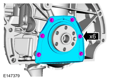
Remove the bolts and the crankshaft rear seal.
 |
Installation
-
NOTE: Make sure that the mating faces are clean and free of foreign material.
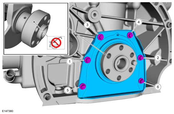
NOTE: The new crankshaft rear seal is supplied with an alignment sleeve which must be removed after installation.
NOTE: Do not remove the alignment sleeve from the crankshaft rear seal prior to installation on the crankshaft.
Install the rear crankshaft seal and the bolts in sequence shown.
Torque:
Stage 1: Tighten bolts 1 through 6 to:: 35 lb.in (4 Nm)
Stage 2: Tighten bolts 1 through 6 to:: 89 lb.in (10 Nm)
 |
-
Install the following items:
-
Install the oil pan.
Refer to: Oil Pan (303-01A Engine - 1.6L Duratec-16V Ti-VCT (88kW/120PS) – Sigma, Removal and Installation).
-
Install the flywheel.
Refer to: Flywheel (303-01A Engine - 1.6L Duratec-16V Ti-VCT (88kW/120PS) – Sigma, Removal and Installation).
-
Install the oil pan.

 Camshafts. Removal and Installation
Special Tool(s) /
General Equipment
303-1532Installer, Camshaft SealTKIT-2010B-FLMTKIT-2010B-ROW
303-393-02Adapter for 303-393TKIT-2012A-FLTKIT-2012A-ROW
303-393ALocking Tool, FlywheelTKIT-2012A-FLTKIT-2012A-ROW
303-409
(T92C-6700-CH)
Remover, Crankshaft SealTKIT-1992-FH/FMH/FLMHTKIT-1993-LMH/MH
303-748Locking Tool, CrankshaftTKIT-2010B-F..
Other information:
Ford Fiesta 2014 - 2019 Service Manual: Front Door Side Impact Sensor. Removal and Installation
Removal WARNING: The following procedure prescribes critical repair steps required for correct restraint system operation during a crash. Follow all notes and steps carefully. Failure to follow step instructions may result in incorrect operation of the restraint system and increases the risk of serious personal injury or death in a crash. NOTE: Removal steps in this..
Ford Fiesta 2014 - 2019 Service Manual: Crankcase Vent Oil Separator. Removal and Installation
Materials Name Specification Engine Oil - SAE 5W-20 - Synthetic Blend Motor OilXO-5W20-Q1SP WSS-M2C945-B1 Removal NOTE: Removal steps in this procedure may contain installation details. Remove the intake manifold. Refer to: Intake Manifold (303-01B Engine - 1.6L EcoBoost (132kW/180PS) – Sigma, Removal and Installation). ..
Categories
- Manuals Home
- Ford Fiesta Service Manual (2014 - 2019)
- Front Suspension
- Engine - 1.6L EcoBoost (132kW/180PS) – Sigma
- Fuel Pump. Removal and Installation
- Manual Transmission, Clutch, Transfer Case and Power Transfer Unit
- Engine System - General Information
Brake Drum. Removal and Installation
Removal
NOTE: Removal steps in this procedure may contain installation details.
 WARNING:
Before beginning any service procedure in this
manual, refer to health and safety warnings in section 100-00 General
Information. Failure to follow this instruction may result in serious
personal injury.
WARNING:
Before beginning any service procedure in this
manual, refer to health and safety warnings in section 100-00 General
Information. Failure to follow this instruction may result in serious
personal injury.
Remove the wheel and tire.
Refer to: Wheel and Tire (204-04A Wheels and Tires, Removal and Installation).
Copyright © 2026 www.fofiesta7.com