Ford Fiesta: Supplemental Restraint System / Clockspring Adjustment. General Procedures
 WARNING:
If the clockspring is not correctly centralized, it may fail
prematurely. If in doubt, repeat the centralizing procedure. Failure to
follow these instructions may increase the risk of serious personal
injury or death in a crash.
WARNING:
If the clockspring is not correctly centralized, it may fail
prematurely. If in doubt, repeat the centralizing procedure. Failure to
follow these instructions may increase the risk of serious personal
injury or death in a crash.
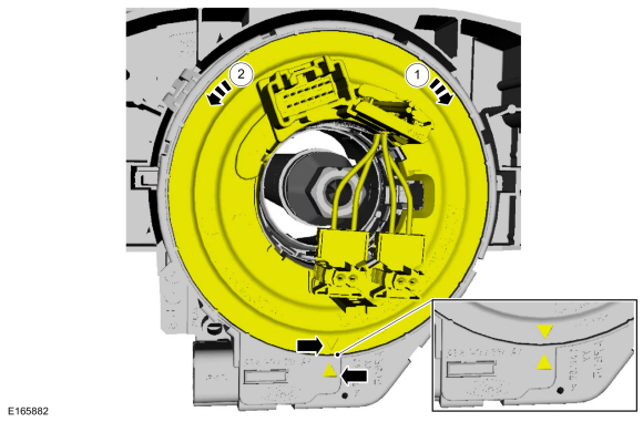
NOTE: Typical clockspring shown, others similar.
-
NOTICE: Do not over-rotate the clockspring inner rotor. The internal ribbon wire is connected to the clockspring rotor. The internal ribbon wire acts as a stop and can be broken from its internal connection. Failure to follow this instruction may result in component damage and/or system failure.
NOTE: After final positioning, do not allow the clockspring rotor to rotate from this position.
-
Turn the rotor clockwise until resistance is felt.
-
Turn the rotor counterclockwise through approximately
3.75 complete turns, until the arrow on the rotor aligns to the arrow on
the housing.
-
Turn the rotor clockwise until resistance is felt.
 |

 Inspection and Repair after a Supplemental Restraint System (SRS) Deployment. General Procedures
Inspection
WARNING:
If a vehicle has been in a crash, inspect the Restraints
Control Module (RCM) and impact sensor mounting areas for any damage or
deformation...
Other information:
Ford Fiesta 2014 - 2019 Service Manual: Exterior Rear Door Handle Reinforcement. Removal and Installation
Removal NOTE: LH side shown, RH side similar. Remove the rear door latch. Refer to: Rear Door Latch (501-14 Handles, Locks, Latches and Entry Systems, Removal and Installation). NOTE: This step is only necessary when installing a new component...
Ford Fiesta 2014 - 2019 Service Manual: Piston. Disassembly and Assembly of Subassemblies
Materials Name Specification Engine Oil - SAE 5W-20 - Synthetic Blend Motor OilXO-5W20-Q1SP WSS-M2C945-B1 DISASSEMBLY Remove and discard the piston rings. Remove and discard the piston pin retainers...
Categories
- Manuals Home
- Ford Fiesta Service Manual (2014 - 2019)
- Lower Arm. Removal and Installation
- Front Strut and Spring Assembly. Removal and Installation
- Valve Cover. Removal and Installation
- Engine
- Maintenance Schedules
Ride Height Measurement. General Procedures
Special Tool(s) / General Equipment
Surface GaugeCheck
Ride Height Measurement - Front
NOTE: Make sure that the vehicle is positioned on a flat, level surface and the tires are inflated to the correct pressure. Vehicle should have a full tank of fuel.
Ride height = 2-3Measurement 2
Measurement 3
Use the General Equipment: Surface Gauge