Ford Fiesta: Supplemental Restraint System / C-Pillar Side Impact Sensor. Removal and Installation
Removal
 WARNING:
The following procedure prescribes critical repair steps
required for correct restraint system operation during a crash. Follow
all notes and steps carefully. Failure to follow step instructions may
result in incorrect operation of the restraint system and increases the
risk of serious personal injury or death in a crash.
WARNING:
The following procedure prescribes critical repair steps
required for correct restraint system operation during a crash. Follow
all notes and steps carefully. Failure to follow step instructions may
result in incorrect operation of the restraint system and increases the
risk of serious personal injury or death in a crash.
NOTE: RH side shown, LH side similar.
NOTE: To avoid damage to the trim panels, remove any retaining clips from the body and attach them to the trim panels before installing.
NOTE: Removal steps in this procedure may contain installation details.
All vehicles
-
Depower the SRS .
Refer to: Supplemental Restraint System (SRS) Depowering and Repowering (501-20B Supplemental Restraint System, General Procedures).
-
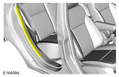
Position aside the rear door weatherstrip.
 |
4-Door
-
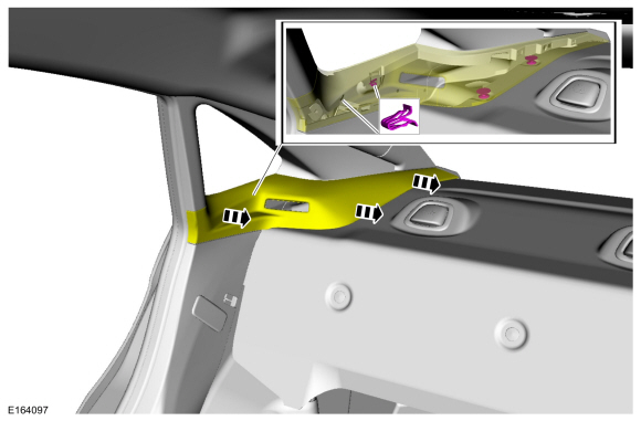
NOTE: Rear seat and safety belt removed for clarity.
Release the clips and position aside the C-pillar upper trim panel.
 |
All vehicles
-
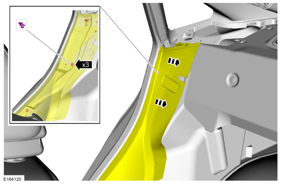
NOTE: 4-door shown, 5-door similar.
Release the clips and position aside the C-pillar lower trim panel.
 |
-
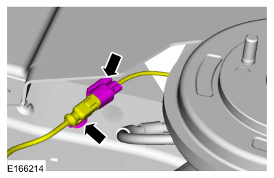
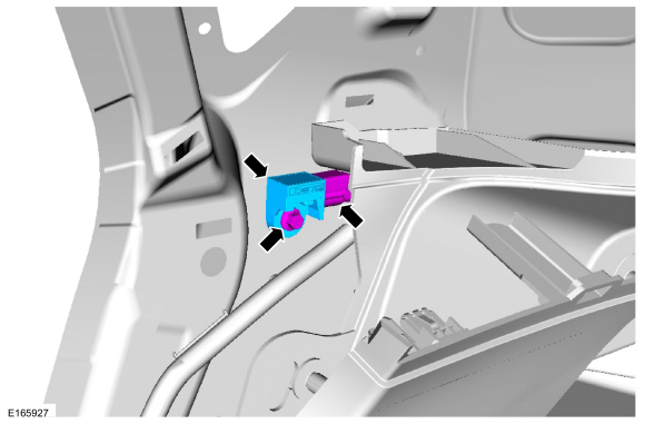
Remove the bolt, disconnect the electrical connector and remove the side impact sensor.
Torque: 93 lb.in (10.5 Nm)
 |
Installation
-
NOTE: Make sure the C-pillar and side impact sensor mating surfaces are clean and free of foreign material.
To install, reverse the removal procedure.
-
Repower the SRS .
Refer to: Supplemental Restraint System (SRS) Depowering and Repowering (501-20B Supplemental Restraint System, General Procedures).
 Clockspring. Removal and Installation
Removal
WARNING:
The following procedure prescribes critical repair steps
required for correct restraint system operation during a crash...
 Driver Airbag. Removal and Installation
Removal
WARNING:
The following procedure prescribes critical repair steps
required for correct restraint system operation during a crash...
Other information:
Ford Fiesta 2014 - 2019 Service Manual: Joining Techniques. General Procedures
Special Tool(s) / General Equipment Resistance Spotwelding Equipment Plasma Cutter Air Body Saw 8 mm Drill Bit MIG/MAG Welding Equipment Spot Weld Drill Bit Materials Name Specification Metal Bonding AdhesiveTA-1, TA-1-B, 3M™ 08115, LORD Fusor® 108B, Henkel Teroson EP 5055 - Seam SealerTA-2-B, 3M™ 08308..
Ford Fiesta 2014 - 2019 Service Manual: Charging System - 1.6L EcoBoost (132kW/180PS) – Sigma - Overview. Description and Operation
Overview The Charging System is a negative ground system consisting of: a generator with an internal voltage regulator. a charging system warning indicator. a battery. a battery monitoring sensor. circuitry and cables. a PCM . The generator is driven by the FEAD belt. When the engine is started, the generator begins to generate AC voltage..
Categories
- Manuals Home
- Ford Fiesta Service Manual (2014 - 2019)
- Engine Cooling - 1.6L EcoBoost (132kW/180PS) – Sigma
- Lower Arm. Removal and Installation
- Front Strut and Spring Assembly. Removal and Installation
- Valve Cover. Removal and Installation
- Maintenance Schedules
Rear Wheel Speed Sensor. Removal and Installation
Removal
NOTE: Removal steps in this procedure may contain installation details.
Remove the retainer and pull the rear splash shield outward.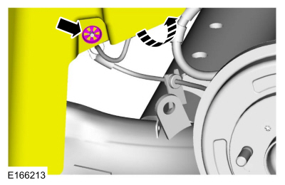 Disconnect the electrical connector and detach the wiring retainer.