Ford Fiesta: Body Repairs - Vehicle Specific Information and Tolerance Checks / Body Panel Sectioning. General Procedures
Special Tool(s) / General Equipment
| Resistance Spotwelding Equipment | |
| Plasma Cutter | |
| Air Body Saw | |
| MIG/MAG Welding Equipment | |
| Spot Weld Drill Bit |
Materials
| Name | Specification |
|---|---|
| Seam Sealer TA-2-B, 3M™ 08308, LORD Fusor® 803DTM |
- |
Repair
NOTICE: Do not begin removal of the vehicle body side until the replacement panel is available for reference.
-
Refer to: Body Repair Health and Safety and General Precautions (100-00 General Information, Description and Operation). WARNING:
Before beginning any service procedure in this
section, REFER to Safety Warnings in section 100-00 General Information.
Failure to follow this instruction may result in serious personal
injury.
WARNING:
Before beginning any service procedure in this
section, REFER to Safety Warnings in section 100-00 General Information.
Failure to follow this instruction may result in serious personal
injury.
-
Detrim the vehicle as necessary and remove spot welds from the damaged area.
Use the General Equipment: Spot Weld Drill Bit
-
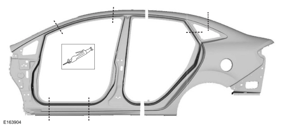
NOTICE: Do not carry out body side sectioning repairs in areas of door hinge or striker anchoring points. Welding within 50 mm (1.96 in) of door hinge or striker locations may compromise structural integrity during a collision.
NOTE: Sectioning within the door hinge portion of the A-pillar, B-pillar or dog leg portion of quarter panel is not approved by Ford Motor Company.
Body side replacement panels are released as 2-part panels. Only remove as much of the body side as necessary.
Use the General Equipment: Air Body Saw
Use the General Equipment: Plasma Cutter
 |
-
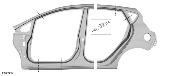
NOTICE: Do not carry out body side sectioning repairs in areas of door hinge or striker anchoring points. Welding within 50 mm (1.96 in) of door hinge or striker locations may compromise structural integrity during a collision.
NOTE: Sectioning within the door hinge portion of the A-pillar, B-pillar or dog leg portion of quarter panel is not approved by Ford Motor Company.
Body side replacement panels are released as 2-part panels. Only remove as much of the body side as necessary.
Use the General Equipment: Air Body Saw
Use the General Equipment: Plasma Cutter
 |
-
NOTE: Use resistance spotwelding equipment where possible. This will produce a higher quality repair.
NOTE: When welding overlapping surfaces or substrates, apply a high quality weld-through primer between the surfaces prior to welding.
Where possible, create a lap-joint backer plate using a portion of the old panel. This will create a stronger joint.
Use the General Equipment: Resistance Spotwelding Equipment
Use the General Equipment: MIG/MAG Welding Equipment
-
Rough finish all sectioning joints with a fibre-based
body filler, final finish sectioning joints and plug welds with a
conventional body filler.
-
Properly seal all horizontal joints to prevent moisture
intrusion. Water and moisture migrate toward horizontal joints and
corrosion tends to occur more rapidly in these areas.
Material: Seam Sealer / TA-2-B, 3M™ 08308, LORD Fusor® 803DTM
-
Proceed with the refinishing process using a Ford approved paint system and manufacturers recommendations.
-
Refer to: Corrosion Prevention (501-25 Body Repairs - General Information, General Procedures).
-
Reinstall vehicle trim as necessary.
 Vehicle Specific Body Construction. Description and Operation
For recommended metal repair guidelines and recommendations, refer to the following illustrations and: For additional information, refer to: Specifications (501-25 Body Repairs - General Information, Specifications)...

Other information:
Ford Fiesta 2014 - 2019 Service Manual: Tie Rod. Removal and Installation
Special Tool(s) / General Equipment Tie Rod End Remover Tie Rod Remover and Installer Boot Clamp Pliers Materials Name Specification Motorcraft® Premium Long-Life GreaseXG-1-E1 ESA-M1C75-B Removal NOTICE: When servicing inner tie rods, install a new bellows boot and clamps. The boots and clamps are designed to provide a..
Ford Fiesta 2014 - 2019 Service Manual: Wheel and Tire. Removal and Installation
Materials Name Specification Motorcraft® High Temperature Nickel Anti-Seize LubricantXL-2 - Removal With the vehicle in NEUTRAL, position it on a hoist. Refer to: Jacking and Lifting - Overview (100-02 Jacking and Lifting, Description and Operation). NOTICE: Do not use heat to loosen a seized wheel nut or damage to the wh..
Categories
- Manuals Home
- Ford Fiesta Service Manual (2014 - 2019)
- Front Strut and Spring Assembly. Removal and Installation
- Front Suspension
- Engine System - General Information
- Manual Transmission - 6-Speed Manual Transmission – B6
- Jacking and Lifting - Overview. Description and Operation
Brake Master Cylinder. Removal and Installation
Removal
NOTICE: If the fluid is spilled on the paintwork, the affected area must be immediately washed down with cold water.
NOTE: Removal steps in this procedure may contain installation details.
All vehicles
Remove the battery tray.Refer to: Battery Tray - 1.6L Duratec-16V Ti-VCT (88kW/120PS) – Sigma (414-01 Battery, Mounting and Cables, Removal and Installation).
Refer to: Battery Tray - 1.6L EcoBoost (132kW/180PS) – Sigma (414-01 Battery, Mounting and Cables, Removal and Installation).
Disconnect the vacuum tube from the brake booster and detach the routing clip.