Ford Fiesta: Multifunction Electronic Modules / Body Control Module (BCM). Removal and Installation
Ford Fiesta 2014 - 2019 Service Manual / Electronic Feature Group / Multifunction Electronic Modules / Body Control Module (BCM). Removal and Installation
Removal
NOTE: Removal steps in this procedure may contain installation details.
-
NOTE: This step is only necessary when installing a new component.
NOTE: The PMI process must begin with the current BCM installed. If the current BCM does not respond to the diagnostic scan tool, the tool may prompt for As-Built Data as part of the repair.
A minimum of 2 RKE transmitter(s) are necessary to complete the configuration. Using the diagnostic scan tool, begin the PMI process for the BCM following the on-screen instructions.
-
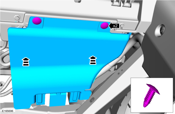
Remove the pin-type retainers and the RH insulation panel.
 |
-
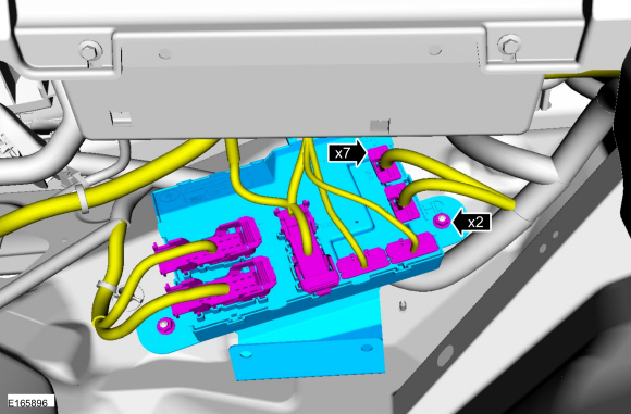
Disconnect the electrical connectors, remove the nuts and the BCM .
 |
Installation
-
Install the BCM , tighten the nuts and connect the electrical connectors.
Torque: 115 lb.in (13 Nm)
|
-
NOTE: If the BCM is not being replaced, this is the last step that is necessary.
Install the RH insulation panel and the pin-type retainers.
 |
-
Using a diagnostic scan tool, begin the PMI process for the BCM following the on-screen instructions.
-
Carry out the BCM self-test to confirm all DTC have been cleared.
-
For vehicles without push button start, program all the RKE transmitter(s) into the new BCM .
Refer to: Remote Keyless Entry (RKE) Transmitter Programming (501-14 Handles, Locks, Latches and Entry Systems, General Procedures).
 Transport and Factory Mode Deactivation. General Procedures
Deactivation
Place the ignition in the OFF position.
Verify the battery is fully charged.
Refer to: Battery (414-01 Battery, Mounting and Cables, Diagnosis and Testing)...
 Remote Function Actuator (RFA) Module. Removal and Installation
Removal
NOTE:
Removal steps in this procedure may contain installation details.
NOTE:
If equipped with push button start the keys need to be programmed into
the new RFA module during ignition off...
Other information:
Ford Fiesta 2014 - 2019 Service Manual: Windshield Wiper Pivot Arm. Removal and Installation
Special Tool(s) / General Equipment Two Leg Puller Removal NOTE: LH side shown, RH side similar. NOTE: Removal steps in this procedure may contain installation details. Remove the windshield wiper pivot arm nut cover and remove the windshield wiper pivot arm nut...
Ford Fiesta 2014 - 2019 Service Manual: Evaporative Emission Canister Purge Valve. Removal and Installation
Removal NOTE: Removal steps in this procedure may contain installation details. Disconnect the battery. Refer to: Battery Disconnect and Connect (414-01 Battery, Mounting and Cables, General Procedures). Remove the air cleaner outlet pipe...
Categories
- Manuals Home
- Ford Fiesta Service Manual (2014 - 2019)
- Manual Transmission - 6-Speed Manual Transmission – B6
- Engine Cooling - 1.6L EcoBoost (132kW/180PS) – Sigma
- Engine. Assembly
- Engine System - General Information
- Manual Transmission, Clutch, Transfer Case and Power Transfer Unit
Brake Drum. Removal and Installation
Removal
NOTE: Removal steps in this procedure may contain installation details.
 WARNING:
Before beginning any service procedure in this
manual, refer to health and safety warnings in section 100-00 General
Information. Failure to follow this instruction may result in serious
personal injury.
WARNING:
Before beginning any service procedure in this
manual, refer to health and safety warnings in section 100-00 General
Information. Failure to follow this instruction may result in serious
personal injury.
Remove the wheel and tire.
Refer to: Wheel and Tire (204-04A Wheels and Tires, Removal and Installation).
Copyright © 2026 www.fofiesta7.com