Ford Fiesta: Auxiliary Climate Control / Auxiliary Climate Control - Overview. Description and Operation
Ford Fiesta 2014 - 2019 Service Manual / Climate Control System / Auxiliary Climate Control / Auxiliary Climate Control - Overview. Description and Operation
Overview
The electric booster heater is a heater element made up of ceramic resistors that is mounted in the heater core and evaporator core housing. It directly heats the airflow into the passenger compartment rapidly in the case of low ambient temperatures.
The electric booster heater system includes the following components:
- Electric booster heater
- Electric booster heater relay 1 and electric booster heater relay 2
- IPC
- HVAC control module

 Auxiliary Climate Control - System Operation and Component Description. Description and Operation
System Operation
Electric Booster Heater
Item
Description
1
HS-CAN
2
Ambient Air Temperature (AAT) sensor
3
Electric booster heater
4
HVAC control module
5
Electric booster heater relay 1
6
Electric booster heater relay 2
7
IPC
8
PCM
9
ECT senso..
Other information:
Ford Fiesta 2014 - 2019 Service Manual: Warning Chimes - System Operation and Component Description. Description and Operation
System Operation System Diagram Item Description 1 HS-CAN 2 MS-CAN 3 Belt-Minder® chime 4 Door ajar chime 5 Headlamps on chime 6 Key-in-ignition chime 7 Parking brake chime 8 Safety belt chime 9 Turn signal on tick-tock tone 10 Ignition switch (without..
Ford Fiesta 2014 - 2019 Service Manual: Evaporator. Removal and Installation
Removal NOTE: Removal steps in this procedure may contain installation details. Remove the instrument panel. Refer to: Instrument Panel (501-12 Instrument Panel and Console, Removal and Installation). Disconnect the electrical connectors, detach the wiring harness retainers and position aside the wiring harness. ..
Categories
- Manuals Home
- Ford Fiesta Service Manual (2014 - 2019)
- Timing Belt. Removal and Installation
- Manual Transmission - 6-Speed Manual Transmission – B6
- Cylinder Head. Removal and Installation
- Fuel Pump. Removal and Installation
- Front Strut and Spring Assembly. Removal and Installation
Front Strut and Spring Assembly. Removal and Installation
Removal
NOTE: Removal steps in this procedure may contain installation details.
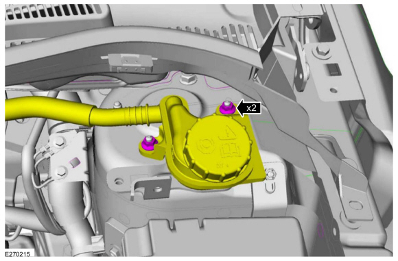
NOTE: This step is only necessary when installing a new component to the left-hand side.
Remove the nuts and position aside the remote brake fluid reservoir.Torque: 62 lb.in (7 Nm)
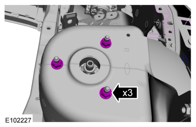
 Remove the strut and spring assembly upper mount nuts.
 Torque: 22 lb.ft (30 Nm)
Copyright © 2026 www.fofiesta7.com