Ford Fiesta: Information and Entertainment System - General Information - Vehicles With: AM/FM/CD/SYNC / Audio Unit Antenna. Removal and Installation
Ford Fiesta 2014 - 2019 Service Manual / Information and Entertainment Systems / Information and Entertainment System - General Information - Vehicles With: AM/FM/CD/SYNC / Audio Unit Antenna. Removal and Installation
Removal
NOTE: Removal steps in this procedure may contain installation details.
-
Lower the headliner.
Refer to: C-Pillar Upper Trim Panel - 4-Door (501-05 Interior Trim and Ornamentation, Removal and Installation).
Refer to: Headliner - 5-Door (501-05 Interior Trim and Ornamentation, Removal and Installation).
-
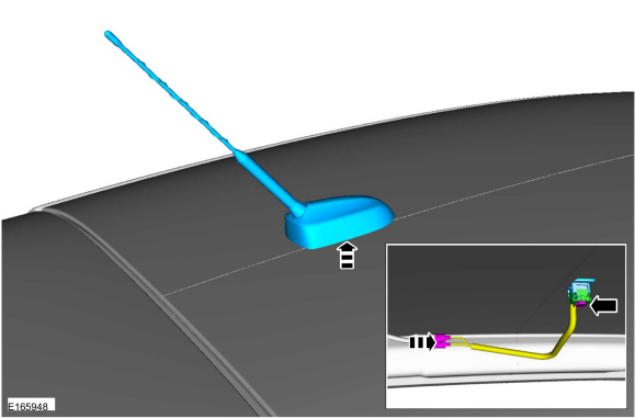
Remove the retainer, audio unit antenna and harness through the roof opening.
-
Disconnect the electrical connectors.
Torque: 80 lb.in (9 Nm)
-
Disconnect the electrical connectors.
 |
Installation
-
To install, reverse the removal procedure.
 SYNC Module [APIM] to Universal Serial Bus (USB) Port Cable. Removal and Installation
Special Tool(s) /
General Equipment
Interior Trim Remover
Removal
All vehicles
Release the retainers and remove the bracket...
 Audio Unit Antenna Cable. Removal and Installation
Special Tool(s) /
General Equipment
Interior Trim Remover
Removal
NOTE:
Removal steps in this procedure may contain installation details...
Other information:
Ford Fiesta 2014 - 2019 Service Manual: Roof Opening Panel Shield. Removal and Installation
Removal NOTE: Removal steps in this procedure may contain installation details. Remove the roof opening panel glass. Refer to: Roof Opening Panel Glass (501-17 Roof Opening Panel, Removal and Installation). NOTICE: Pull up on the center of the shade only enough to disengage the foot from the track...
Ford Fiesta 2014 - 2019 Service Manual: Piston Inspection. General Procedures
Inspection NOTE: Do not use a caustic cleaning solution or a wire brush to clean the pistons or damage can occur. Clean and inspect the (1) ring lands, (2) pin bosses, (3) skirts and the (4) tops of the pistons. If wear marks, scores or glazing is found on the piston skirt, check for a bent or twisted connecting rod...
Categories
- Manuals Home
- Ford Fiesta Service Manual (2014 - 2019)
- Engine - 1.6L EcoBoost (132kW/180PS) – Sigma
- Front Strut and Spring Assembly. Removal and Installation
- Jacking and Lifting - Overview. Description and Operation
- Valve Cover. Removal and Installation
- Manual Transmission - 6-Speed Manual Transmission – B6
Front Strut and Spring Assembly. Removal and Installation
Removal
NOTE: Removal steps in this procedure may contain installation details.
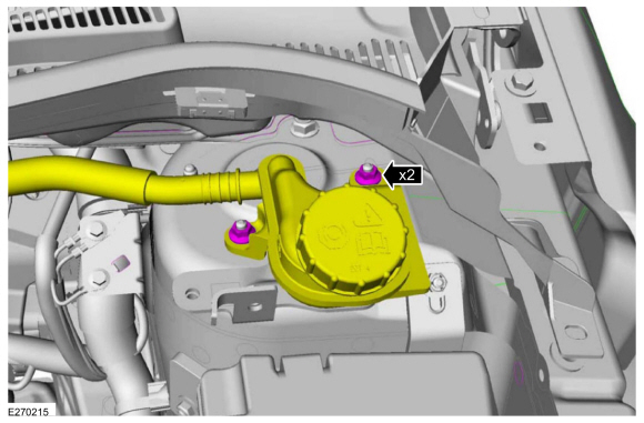
NOTE: This step is only necessary when installing a new component to the left-hand side.
Remove the nuts and position aside the remote brake fluid reservoir.Torque: 62 lb.in (7 Nm)
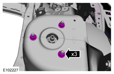
 Remove the strut and spring assembly upper mount nuts.
 Torque: 22 lb.ft (30 Nm)
Copyright © 2026 www.fofiesta7.com