Ford Fiesta: Fuel Charging and Controls - 1.6L EcoBoost (132kW/180PS) – Sigma / Throttle Body. Removal and Installation
Ford Fiesta 2014 - 2019 Service Manual / Engine / Fuel Charging and Controls - 1.6L EcoBoost (132kW/180PS) – Sigma / Throttle Body. Removal and Installation
Removal
NOTE: Removal steps in this procedure may contain installation details.
-
Refer to: Jacking and Lifting - Overview (100-02 Jacking and Lifting, Description and Operation).
-
-
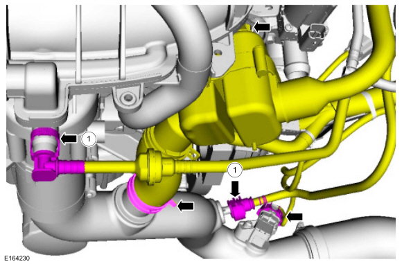
Disconnect the quick release couplings.
Refer to: Quick Release Coupling (310-00B Fuel System - General
Information - 1.6L EcoBoost (132kW/180PS) – Sigma, General Procedures).
-
Release the resonator assembly from the retainer,
release the resonator assembly clamp and then position the resonator
assembly out of the way.
-
Disconnect the quick release couplings.
Refer to: Quick Release Coupling (310-00B Fuel System - General
Information - 1.6L EcoBoost (132kW/180PS) – Sigma, General Procedures).
 |
-
-
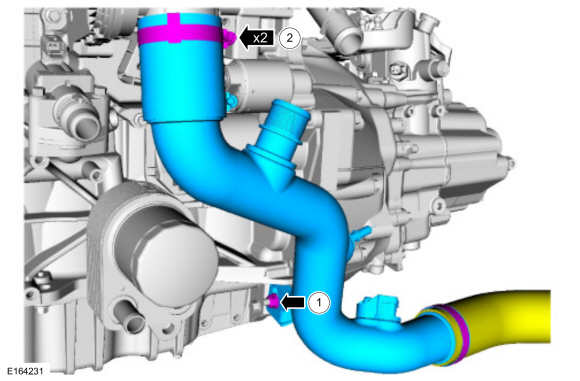
Remove the CAC outlet pipe retaining nut.
Torque: 133 lb.in (15 Nm)
-
Loosen the CAC outlet pipe clamps and then remove the CAC outlet pipe.
Torque: 44 lb.in (5 Nm)
-
Remove the CAC outlet pipe retaining nut.
 |
-
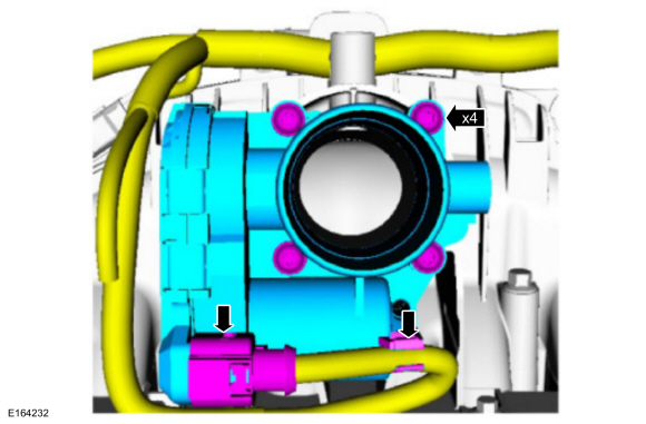
NOTE: Tighten the Throttle Body (TB) mounting bolts evenly.
-
Disconnect the Throttle Body electrical connector
and detach the Throttle Body wiring harness retainer from the Throttle
Body.
-
Remove the Throttle Body bolts and then remove the Throttle Body.
Torque: 71 lb.in (8 Nm)
-
Disconnect the Throttle Body electrical connector
and detach the Throttle Body wiring harness retainer from the Throttle
Body.
 |
-
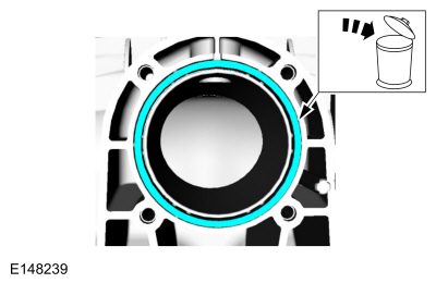
Remove and discard the Throttle Body gasket.
 |
Installation
NOTICE: Make sure that the mating faces are clean and free of foreign material.
-
To install, reverse the removal procedure.


Other information:
Ford Fiesta 2014 - 2019 Service Manual: Clutch Controls. Diagnosis and Testing
Inspection and Verification NOTICE: If transmission noise is reported, first check the transmission fluid level. The vehicle should not be driven if the transmission fluid level is low. A low transmission fluid level will damage the transmission. NOTE: Before attempting to repair any concerns, road test the vehicle to determine which system the concern is in. NOTE: If ..
Ford Fiesta 2014 - 2019 Service Manual: Specifications
SPECIFICATIONS Torque Specifications Description Nm lb-ft lb-in Rear seat backrest hinge bolts a 40 30 - Rear seat backrest striker bolts 25 18 - aDiscard and install new...
Categories
- Manuals Home
- Ford Fiesta Service Manual (2014 - 2019)
- Service Information
- Maintenance Schedules
- Engine. Assembly
- Clutch - 6-Speed Manual Transmission – B6
- Fuel Pump. Removal and Installation
Ride Height Measurement. General Procedures
Special Tool(s) / General Equipment
Surface GaugeCheck
Ride Height Measurement - Front
NOTE: Make sure that the vehicle is positioned on a flat, level surface and the tires are inflated to the correct pressure. Vehicle should have a full tank of fuel.
Ride height = 2-3Measurement 2
Measurement 3
Use the General Equipment: Surface Gauge
Copyright © 2026 www.fofiesta7.com