Ford Fiesta: Parking Brake and Actuation / Parking Brake Cable Adjustment. General Procedures
Ford Fiesta 2014 - 2019 Service Manual / Brake System / Parking Brake and Actuation / Parking Brake Cable Adjustment. General Procedures
Special Tool(s) / General Equipment
 |
206-D002
(D81L-1103-A)
Gauge, Brake Adjustment |
Adjustment
-
Remove the floor console.
Refer to: Floor Console (501-12 Instrument Panel and Console, Removal and Installation).
-
Remove the parking brake cable adjustment lock nut.
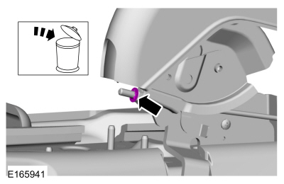 |
-
Loosen the parking brake cable adjustment nut.
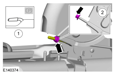 |
-
Remove the rear wheels and tires.
Refer to: Wheel and Tire (204-04A Wheels and Tires, Removal and Installation).
-
Remove the brake drums.
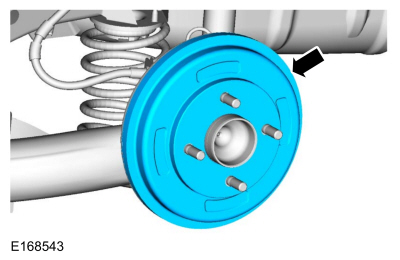 |
-
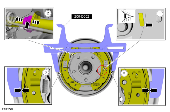
Using the caliper gauge, measure the inside diameter of the brake drums.
Use Special Service Tool: 206-D002 (D81L-1103-A) Gauge, Brake Adjustment.
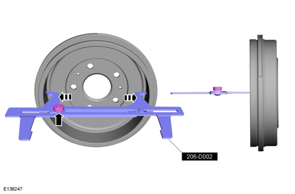 |
-
-
Check to make sure the abutment on the parking brake levers are resting on the brake shoes.
-
Rotate the adjusters in or out as necessary to obtain the correct adjustment.
-
Using the special tool, make sure the brake shoes
are correctly adjusted. The brake shoe linings should make light contact
with the arms on the special tool.
Use Special Service Tool: 206-D002 (D81L-1103-A) Gauge, Brake Adjustment.
-
Check to make sure the abutment on the parking brake levers are resting on the brake shoes.
 |
-
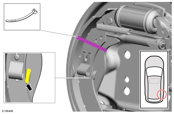
Install a cable tie on the RH rear brake shoe and the parking brake lever.
 |
-
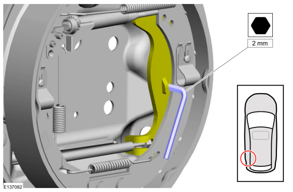
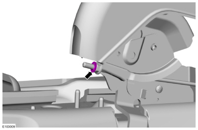
Install a 2mm hex wrench between the abutment on the LH parking brake lever and the brake shoe.
 |
-
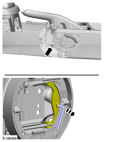
Tighten the parking brake cable adjustment nut until the hex wrench falls.
 |
-
Cut and remove the cable tie.
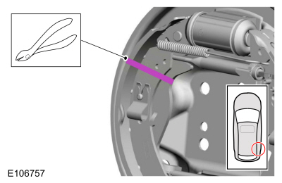 |
-
Install the brake drums.
|
-
Install the parking brake cable adjustment lock nut.
 |
-
Install the rear wheels and tires.
Refer to: Wheel and Tire (204-04A Wheels and Tires, Removal and Installation).
-
Install the floor console.
Refer to: Floor Console (501-12 Instrument Panel and Console, Removal and Installation).
 Parking Brake. Diagnosis and Testing
Symptom Chart(s)
Symptom Chart: Parking Brake and Actuation
Diagnostics in this manual assume a certain skill level and knowledge of Ford-specific diagnostic practices...
 Parking Brake Cable Adjustment - 1.6L EcoBoost (132kW/180PS) – Sigma. General Procedures
Special Tool(s) /
General Equipment
Feeler Gauge
Adjustment
Remove the floor console.
Refer to: Floor Console (501-12 Instrument Panel and Console, Removal and Installation)...
Other information:
Ford Fiesta 2014 - 2019 Service Manual: Throttle Body. Removal and Installation
Removal NOTE: Removal steps in this procedure may contain installation details. Refer to: Jacking and Lifting - Overview (100-02 Jacking and Lifting, Description and Operation). Disconnect the quick release couplings...
Ford Fiesta 2014 - 2019 Service Manual: Front Fog Lamp. Removal and Installation
Removal With the vehicle in NEUTRAL, position it on a hoist. Refer to: Jacking and Lifting - Overview (100-02 Jacking and Lifting, Description and Operation). Remove the appropriate wheel and tire. Refer to: Wheel and Tire (204-04A Wheels and Tires, Removal and Installation)...
Categories
- Manuals Home
- Ford Fiesta Service Manual (2014 - 2019)
- Camshafts. Removal and Installation
- Cylinder Head. Removal and Installation
- Engine System - General Information
- Engine - 1.6L EcoBoost (132kW/180PS) – Sigma
- Engine Cooling - 1.6L EcoBoost (132kW/180PS) – Sigma
Brake Drum. Removal and Installation
Removal
NOTE: Removal steps in this procedure may contain installation details.
 WARNING:
Before beginning any service procedure in this
manual, refer to health and safety warnings in section 100-00 General
Information. Failure to follow this instruction may result in serious
personal injury.
WARNING:
Before beginning any service procedure in this
manual, refer to health and safety warnings in section 100-00 General
Information. Failure to follow this instruction may result in serious
personal injury.
Remove the wheel and tire.
Refer to: Wheel and Tire (204-04A Wheels and Tires, Removal and Installation).
Copyright © 2026 www.fofiesta7.com