Ford Fiesta: Rear End Sheet Metal Repairs / Inner Quarter Panel and Wheelhouse - 5-Door. Removal and Installation
Ford Fiesta 2014 - 2019 Service Manual / Body and Paint / Rear End Sheet Metal Repairs / Inner Quarter Panel and Wheelhouse - 5-Door. Removal and Installation
Special Tool(s) / General Equipment
| Resistance Spotwelding Equipment | |
| Air Body Saw | |
| MIG/MAG Welding Equipment | |
| Spot Weld Drill Bit | |
| Locking Pliers |
Materials
| Name | Specification |
|---|---|
| Seam Sealer TA-2-B, 3M™ 08308, LORD Fusor® 803DTM |
- |
Removal
-
Follow the health and safety precautions. WARNING:
Before beginning any service procedure in this
manual, refer to health and safety warnings in section 100-00 General
Information. Failure to follow this instruction may result in serious
personal injury.
WARNING:
Before beginning any service procedure in this
manual, refer to health and safety warnings in section 100-00 General
Information. Failure to follow this instruction may result in serious
personal injury.
Refer to: Body Repair Health and Safety and General Precautions (100-00 General Information, Description and Operation).
-
For vehicle dimensional information:
Refer to: Body and Frame (501-26 Body Repairs - Vehicle Specific Information and Tolerance Checks, Description and Operation).
-
Remove the following items.
Refer to: Quarter Panel LH - 5-Door (501-30 Rear End Sheet Metal Repairs, Removal and Installation).
Refer to: Water Drain Panel - 5-Door (501-30 Rear End Sheet Metal Repairs, Removal and Installation).
-
Reposition the carpeting and the wiring harness away from the working area.
-
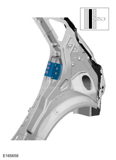
Drill out the spot welds and remove the reinforcement bracket.
Use the General Equipment: Spot Weld Drill Bit
 |
-
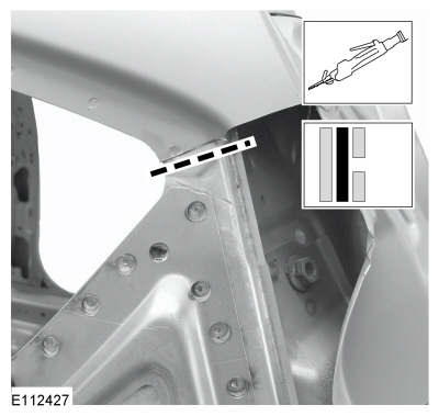
Drill out the spot welds and carefully cut the outer section.
Use the General Equipment: Spot Weld Drill Bit
Use the General Equipment: Air Body Saw
 |
-
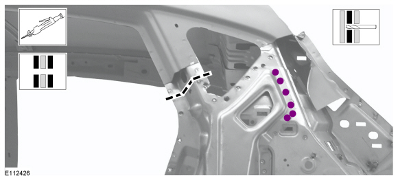
Remove the spot welds and the reinforcement side panel.
Use the General Equipment: Spot Weld Drill Bit
 |
-
Drill out the spot welds.
Use the General Equipment: Spot Weld Drill Bit
 |
-
Carefully cut the outer section.
Use the General Equipment: Air Body Saw
 |
-
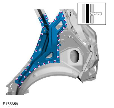
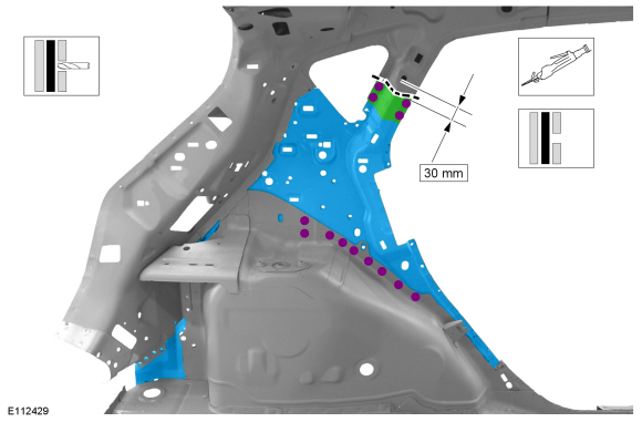
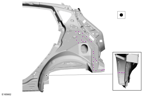
Drill out the spot welds and carefully measure and cut the inner quarter panel and wheelhouse only and remove.
Use the General Equipment: Spot Weld Drill Bit
Use the General Equipment: Air Body Saw
 |
Installation
-
Carefully measure and cut the replacment panels to fit repair area.
Use the General Equipment: Air Body Saw
-
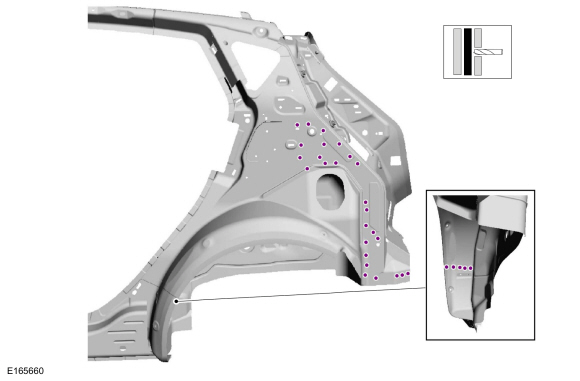
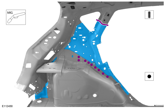
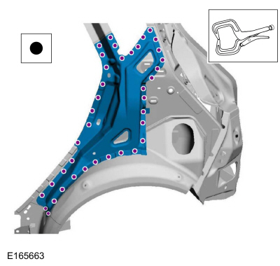
Install the inner quarter panel and wheelhouse, spot welds and seam weld the section.
Use the General Equipment: MIG/MAG Welding Equipment
Use the General Equipment: Resistance Spotwelding Equipment
 |
-
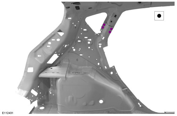
Install the spot welds.
Use the General Equipment: Resistance Spotwelding Equipment
 |
-
Install the spot welds.
Use the General Equipment: Resistance Spotwelding Equipment
 |
-
Install the reinforcement side panel and spot welds.
Use the General Equipment: Locking Pliers
Use the General Equipment: Resistance Spotwelding Equipment
 |
-
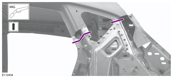
Seam weld.
Use the General Equipment: MIG/MAG Welding Equipment
 |
-
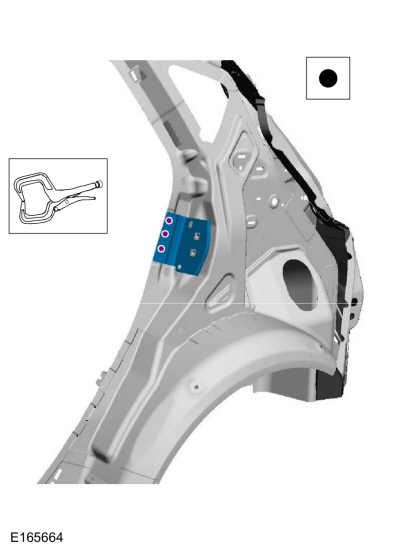
Install the reinforcement bracket and spot welds.
Use the General Equipment: Resistance Spotwelding Equipment
 |
-
Metal finish as required using typical metal finishing techniques.
-
Sealing work: All areas must be sealed to production level.
Material: Seam Sealer / TA-2-B, 3M™ 08308, LORD Fusor® 803DTM
-
Refinish using a Ford approved paint system.
-
Reposition the carpeting and wiring harness.
-
Restore corrosion protection.
Refer to: Corrosion Prevention (501-25 Body Repairs - General Information, General Procedures).
-
Install the following items.
Refer to: Quarter Panel LH - 5-Door (501-30 Rear End Sheet Metal Repairs, Removal and Installation).
Refer to: Water Drain Panel - 5-Door (501-30 Rear End Sheet Metal Repairs, Removal and Installation).

 Back Panel and Reinforcement - 5-Door. Removal and Installation
Special Tool(s) /
General Equipment
Resistance Spotwelding Equipment
Spherical Cutter
8 mm Drill Bit
MIG/MAG Welding Equipment
Spot Weld Drill Bit
Materials
Name
Specification
Seam SealerTA-2-B, 3M™ 08308, LORD Fusor® 803DTM
-
Removal
WARNING:
Before beginning any service procedure in thi..
Other information:
Ford Fiesta 2014 - 2019 Service Manual: Cruise Control - System Operation and Component Description. Description and Operation
System Diagram Item Description 1 IPC 2 Clutch pedal switch 3 Cruise control switches 4 Accelerator pedal 5 BPP switch 6 Deactivator switch 7 PCM 8 ABS module 9 Stoplamp switch 10 HS-CAN System Operation Network Message Chart ..
Ford Fiesta 2014 - 2019 Service Manual: Pinpoint Test - DTC: U. Diagnosis and Testing
B1414:11, B1414:93, B1419:11, B1419:93 Refer to Wiring Diagrams Cell 46 for schematic and connector information. Normal Operation and Fault Conditions The RCM monitors the driver front door and RH C-pillar side impact sensors and circuits for the following faults: Open circuit Short to voltage Short to ground Faulted driver front door ..
Categories
- Manuals Home
- Ford Fiesta Service Manual (2014 - 2019)
- Manual Transmission - 6-Speed Manual Transmission – B6
- Jacking and Lifting - Overview. Description and Operation
- Engine Component View. Description and Operation
- Engine Cooling - 1.6L EcoBoost (132kW/180PS) – Sigma
- Fuel Pump. Removal and Installation
Brake Drum. Removal and Installation
Removal
NOTE: Removal steps in this procedure may contain installation details.
 WARNING:
Before beginning any service procedure in this
manual, refer to health and safety warnings in section 100-00 General
Information. Failure to follow this instruction may result in serious
personal injury.
WARNING:
Before beginning any service procedure in this
manual, refer to health and safety warnings in section 100-00 General
Information. Failure to follow this instruction may result in serious
personal injury.
Remove the wheel and tire.
Refer to: Wheel and Tire (204-04A Wheels and Tires, Removal and Installation).
Copyright © 2026 www.fofiesta7.com