Ford Fiesta: Manual Transmission - 6-Speed Manual Transmission – B6 / Halfshaft Seal LH. Removal and Installation
Special Tool(s) / General Equipment
 |
308-880 Installer, Driveshaft Seal |
Removal
-
Remove the wheel and tire.
Refer to: Wheel and Tire (204-04A Wheels and Tires, Removal and Installation).
-
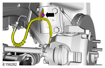
Remove the bolt and position aside the LH brake hose.
 |
-
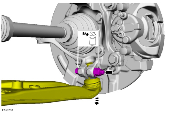
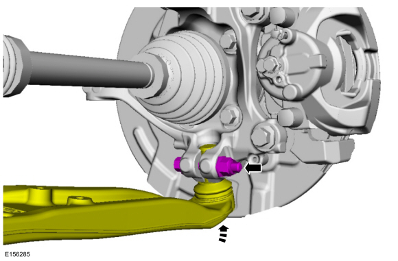
NOTICE: Do not use a prying device or separator fork between the ball joint and the wheel knuckle. Damage to the ball joint or ball joint seal may result. Only use the pry bar by inserting it into the lower arm body opening.
NOTICE: Use care when releasing the lower arm and wheel knuckle into the resting position or damage to the ball joint seal may occur.
Remove and discard the wheel knuckle bolt and the nut. Disconnect the lower arm and position aside the wheel knuckle.
 |
-
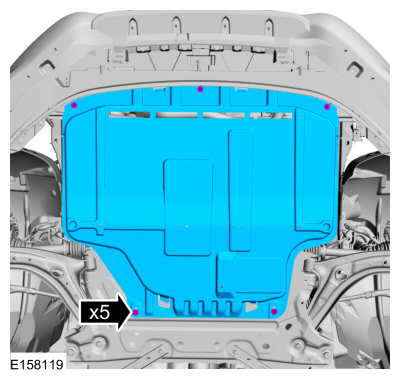
If equipped.
Remove the retainers and the underbody shield.
 |
-
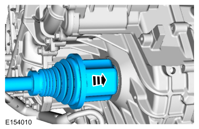
Remove the halfshaft from the transmission and position it aside.
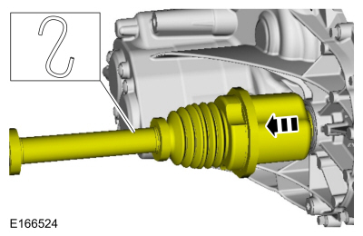 |
-
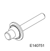
Remove and discard the halfshaft seal.
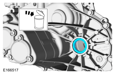 |
Installation
-
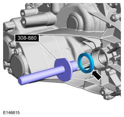
Using the special tool install the halfshaft seal.
Use Special Service Tool: 308-880 Installer, Driveshaft Seal.
 |
-
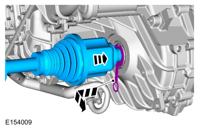
NOTE: Do not fully install shaft at this time.
-
Using part: AA5P-4N206-A.
Pull the LH halfshaft outward to make sure the circlip is locked.
-
Remove the special tool before completely installing the halfshaft.
-
Using part: AA5P-4N206-A.
 |
-
NOTE: Insert shaft until circlip is fully seated. When checking if circlip is seated do not pull on CV joints or damage can result.
Fully insert the halfshaft until the circlip is seated.
 |
-
Insert the lower ball joint into the wheel knuckle and install a new lower ball joint bolt and nut.
Torque: 38 lb.ft (52 Nm)
 |
-
Install the LH brake hose on the strut.
Torque: 19 lb.ft (26 Nm)
|
-
Check the transmission fluid level.
Refer to: Transmission Fluid Level Check (308-03B Manual Transmission - 6-Speed Manual Transmission – B6, General Procedures).
-
If equipped.
Install the underbody shield and the retainers.
|
-
Install the wheel and tire.
Refer to: Wheel and Tire (204-04A Wheels and Tires, Removal and Installation).

 Halfshaft Seal RH. Removal and Installation
Special Tool(s) /
General Equipment
308-880Installer, Driveshaft Seal
Removal
Remove the wheel and tire.
Refer to: Wheel and Tire (204-04A Wheels and Tires, Removal and Installation)...
Other information:
Ford Fiesta 2014 - 2019 Service Manual: Gearshift Lever. Removal and Installation
Removal Remove the floor console. Refer to: Floor Console (501-12 Instrument Panel and Console, Removal and Installation). Disconnect the gearshift cable ends from the ball studs, slide the lock sleeve and remove the gearshift cables from the gearshift lever...
Ford Fiesta 2014 - 2019 Service Manual: Pinpoint Test - DTC: J. Diagnosis and Testing
B0082:11, B0082:12, B0082:13 and B0082:1A Refer to Wiring Diagrams Cell 46 for schematic and connector information. Normal Operation and Fault Conditions The RCM continuously monitors the passenger safety belt load limiter circuits for the following faults: Resistance out of range Unexpected voltage Short to ground Faulted passenger safet..
Categories
- Manuals Home
- Ford Fiesta Service Manual (2014 - 2019)
- Jacking and Lifting - Overview. Description and Operation
- Maintenance Schedules
- Cylinder Head. Removal and Installation
- Engine Component View. Description and Operation
- Manual Transmission, Clutch, Transfer Case and Power Transfer Unit
Brake Master Cylinder. Removal and Installation
Removal
NOTICE: If the fluid is spilled on the paintwork, the affected area must be immediately washed down with cold water.
NOTE: Removal steps in this procedure may contain installation details.
All vehicles
Remove the battery tray.Refer to: Battery Tray - 1.6L Duratec-16V Ti-VCT (88kW/120PS) – Sigma (414-01 Battery, Mounting and Cables, Removal and Installation).
Refer to: Battery Tray - 1.6L EcoBoost (132kW/180PS) – Sigma (414-01 Battery, Mounting and Cables, Removal and Installation).
Disconnect the vacuum tube from the brake booster and detach the routing clip.