Ford Fiesta: Engine - 1.6L EcoBoost (132kW/180PS) – Sigma / Engine. Disassembly
Special Tool(s) /
General Equipment
 |
100-001
(T50T-100-A)
Slide Hammer |
 |
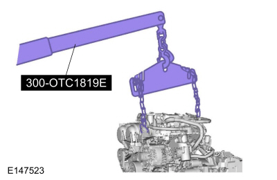
300-OTC1819E
2,200# Floor Crane, Fold Away |
 |
303-1097
Locking Tool, Variable Camshaft Timing Oil Control Unit
TKIT-2010B-FLM
TKIT-2010B-ROW |
 |
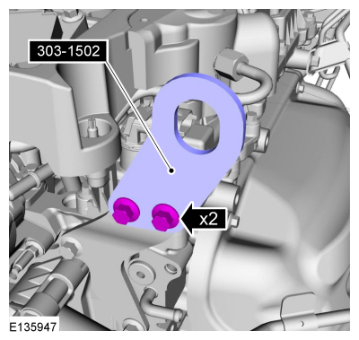
303-1502
Lifting Device Engine
TKIT-2012A-FL
TKIT-2012A-ROW |
 |
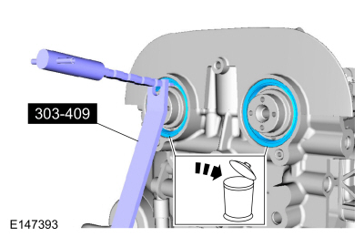
303-409
(T92C-6700-CH)
Remover, Crankshaft Seal
TKIT-1992-FH/FMH/FLMH
TKIT-1993-LMH/MH |
 |
303-748
Locking Tool, Crankshaft
TKIT-2010B-FLM
TKIT-2010B-ROW |
 |
307-005
(T59L-100-B)
Slide Hammer |
 |
308-375
Remover, Input Shaft Seal
TKIT-2005U-M
TKIT-1999-F/FLM/LT |
 |
310-206
Remover, Fuel Injector
TKIT-2009A-FLM |
| Hot Air Gun |
| Hose Clamp Remover/Installer |
Materials
| Name |
Specification |
Motorcraft® Metal Brake Parts Cleaner
PM-4-A, PM-4-B, APM-4-C |
-
|
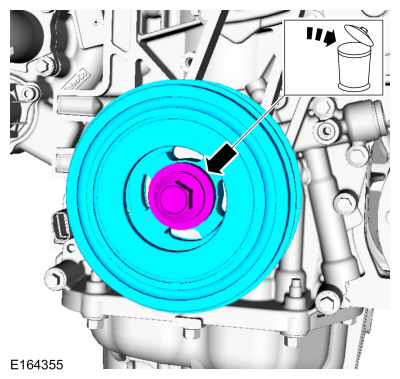
NOTICE:
Do not loosen or remove the crankshaft pulley bolt without first
installing the special tools. The crankshaft pulley and the crankshaft
timing sprocket are not keyed to the crankshaft. Before any repair
requiring loosening or removal of the crankshaft pulley bolt, the
crankshaft and camshafts must be locked in place by the special service
tools, otherwise severe engine damage can occur.
NOTICE:
During engine repair procedures, cleanliness is extremely
important. Any foreign material, including any material created while
cleaning gasket surfaces that enters the oil passages, coolant passages
or the oil pan, can cause engine failure.
NOTE:
Refer to exploded views in Description and Operation.
-
NOTICE:
Do not breathe dust or use compressed air to blow dust
from storage containers or friction components. Remove dust using
government-approved techniques. Friction component dust may be a cancer
and lung disease hazard. Exposure to potentially hazardous components
may occur if dusts are created during repair of friction components,
such as brake pads and clutch discs. Exposure may also cause irritation
to skin, eyes and respiratory tract, and may cause allergic reactions
and/or may lead to other chronic health effects. If irritation persists,
seek medical attention or advice. Failure to follow these instructions
may result in serious personal injury.
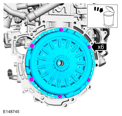
Loosen the 6 clutch pressure plate-to-flywheel bolts evenly, by 2 turns at a time.
-
-
-
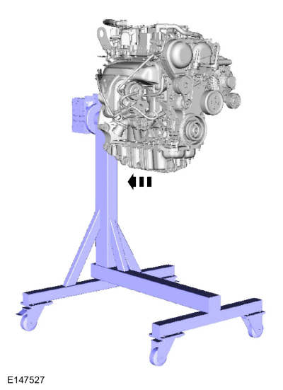
Remove Special Service Tool: 300-OTC1819E
2,200# Floor Crane, Fold Away.
-
Remove Special Service Tool: 303-1502
Lifting Device Engine.
-
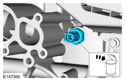
If equipped with block heater.
-
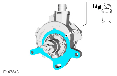
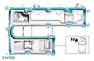
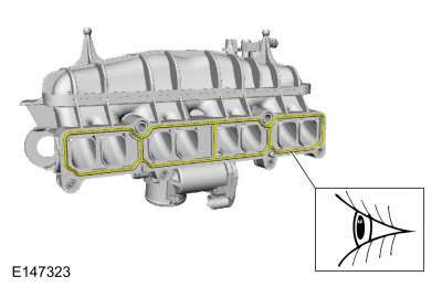
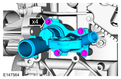
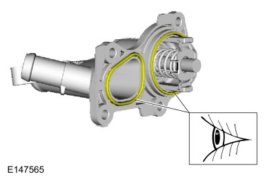
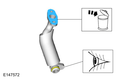
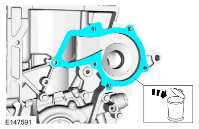
NOTE:
Discard the O-ring seals and gasket seals.
-
-
If equipped.
-
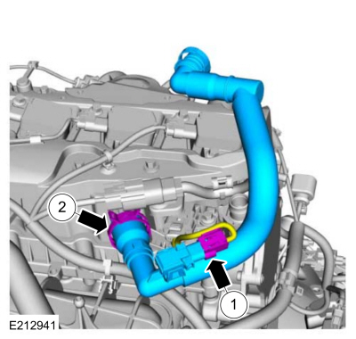
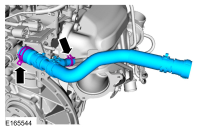
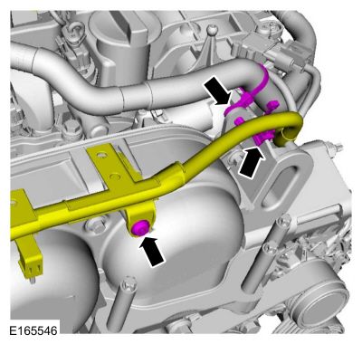
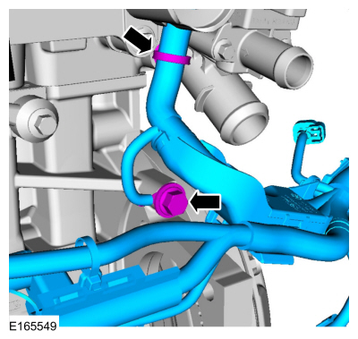
Use the General Equipment: Hose Clamp Remover/Installer
-
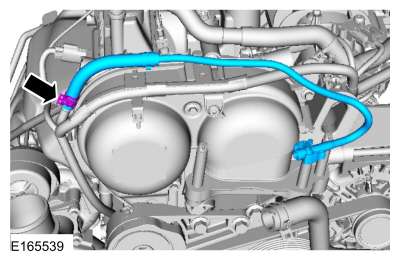
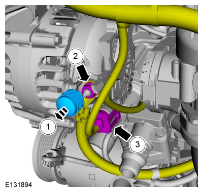
Use the General Equipment: Hose Clamp Remover/Installer
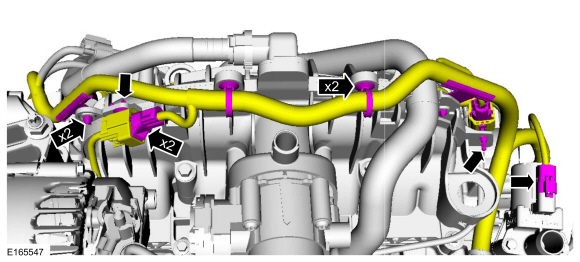
-
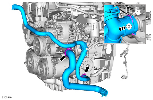
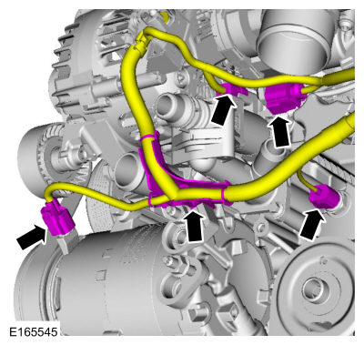
Use the General Equipment: Hose Clamp Remover/Installer
-
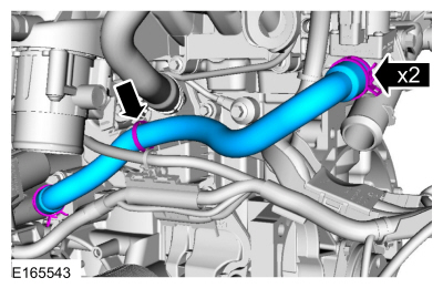
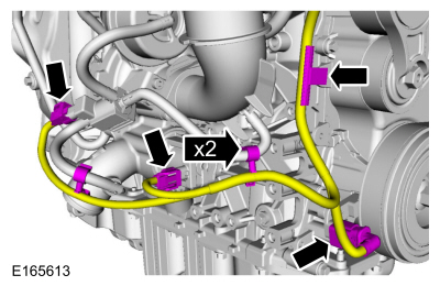
Use the General Equipment: Hose Clamp Remover/Installer
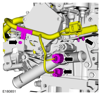
-
Use the General Equipment: Hose Clamp Remover/Installer
-
Use the General Equipment: Hose Clamp Remover/Installer
-
-
-
-
-
-
-
-
-
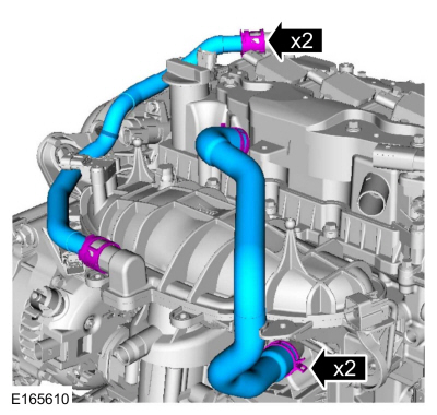
Use the General Equipment: Hose Clamp Remover/Installer
-
-
-
-
-
-
-
-
-
-
-
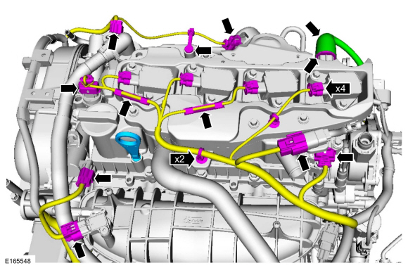
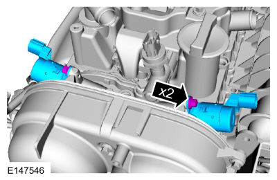
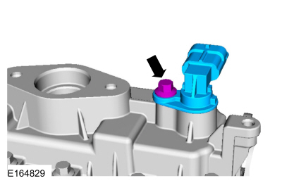
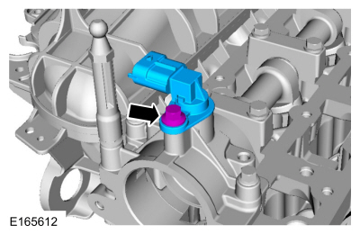
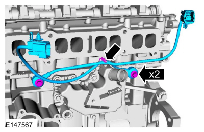
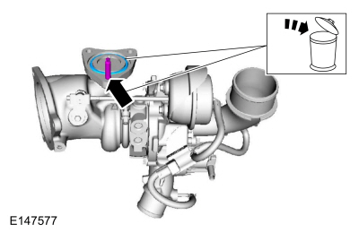
NOTE:
Note the position of the component before removal.
-
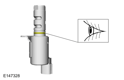
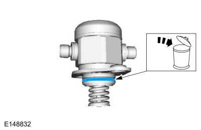
NOTE:
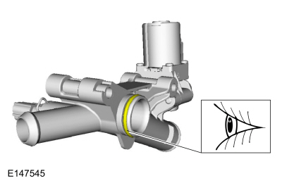
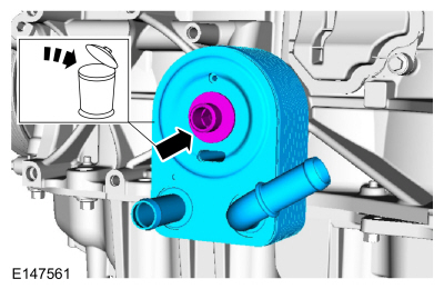
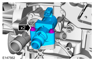
The O-ring seals are to be reused unless damaged.
-
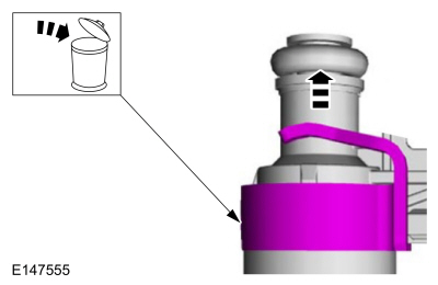
NOTICE:
When removing or installing the fuel injection pump
noise insulator, spreading the openings will reduce the risk of damage.
-
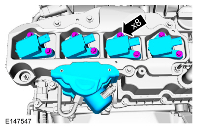
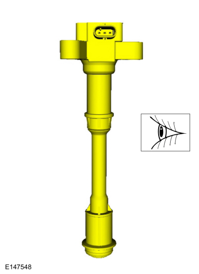
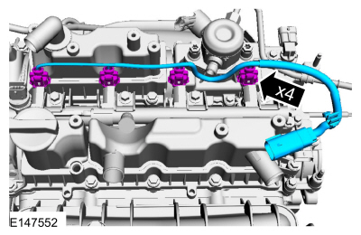
NOTE:
Replace any damaged coil-on-plug assemblies.
-
-
-
-
-
-
-
-
-
-
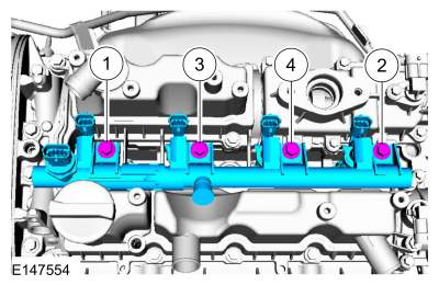
NOTICE:
Pull out the fuel rails in the direction of the fuel injector axis or damage may occur to the fuel injectors.
NOTE:
Use compressed air and remove any dirt or foreign
material from the cylinder head, block and general surrounding area of
the fuel rail and injectors.
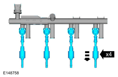
NOTE:
When removing the fuel rails, the fuel injectors may
remain in the fuel rails but normally remain in the cylinder heads and
require the use of a Fuel Injector Remover tool to extract.
-
NOTE:
Take extra care when handling the components.
Remove any of the fuel injectors that remained in the fuel rail.
-
-
NOTE:
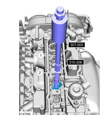
Remove the fuel injectors that remained in the head.
-
Use Special Service Tool: 307-005
(T59L-100-B)
Slide Hammer.
-
Use Special Service Tool: 310-206
Remover, Fuel Injector.
-
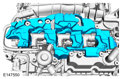
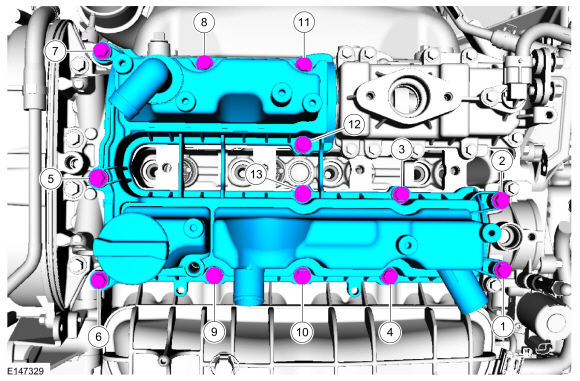
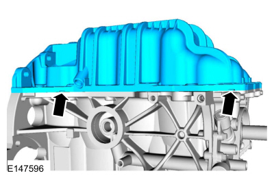
NOTICE:
Do not set the valve cover sealing surface face down on a
bench as the check valve and splitter leg is susceptible to breakage.
-
-
-
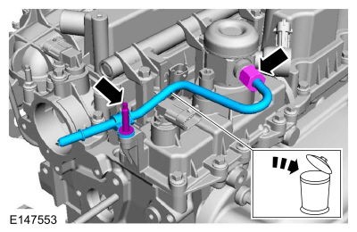
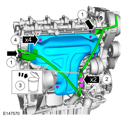
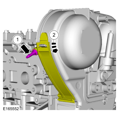
NOTICE:
Use a heat gun to soften the flange sealant, this will
aid in the removal of the fuel pump mounting bracket. Failure to follow
these directions may result in damage to the fuel pump mounting bracket.
Use the General Equipment: Hot Air Gun
-
-
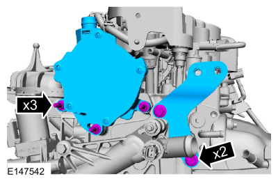
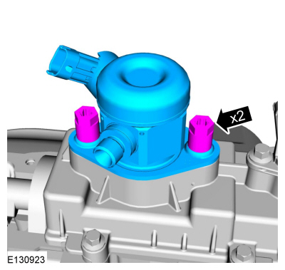
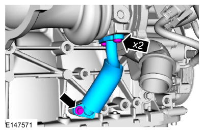
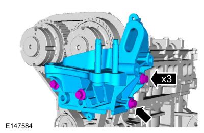
NOTICE:
Use a heat gun to soften the flange sealant, this will
aid in the removal of the brake vacuum pump mounting bracket. Failure to
follow these directions may result in damage to the brake vacuum pump
mounting bracket.
Use the General Equipment: Hot Air Gun
-
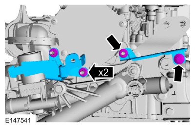
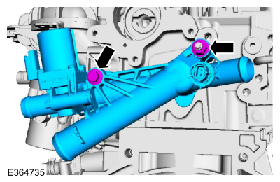
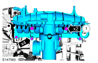
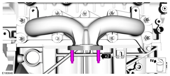
NOTE:
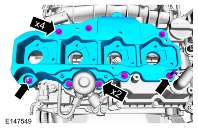
Note the different lengths of the bolts.
-
-
-
-
-
-
-
-
NOTE:
Note the position for installation.
-
-
-
-
-
-
-
-
-
-
-
-
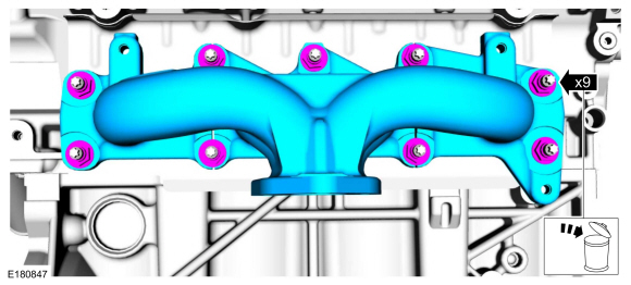
Refer to: Exhaust Manifold Cleaning and Inspection (303-00 Engine System - General Information, General Procedures).
-
-
NOTE:
Note the position for installation.
If equipped with block heater.
-
-
-
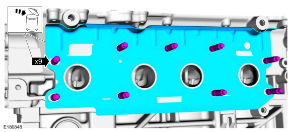
NOTE:
Note the different lengths of the bolts.
-
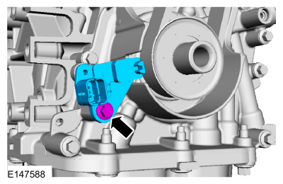
NOTE:
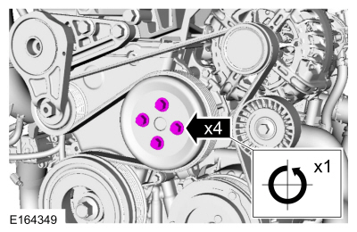
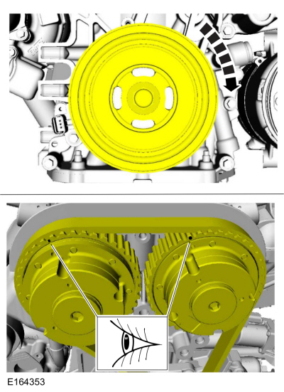
Only rotate the crankshaft in a clockwise direction.
11 o'clock position.
-
-
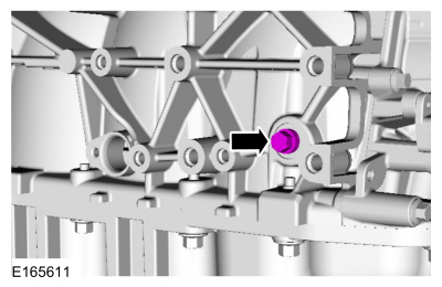
NOTE:
The Crankshaft TDC Timing Pin will contact the crankshaft and prevent
it from turning past TDC . However, the crankshaft can still be rotated
in the counterclockwise direction. The crankshaft must remain at the TDC
position during the crankshaft pulley removal and installation.
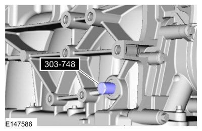
Install Special Service Tool: 303-748
Locking Tool, Crankshaft.
-
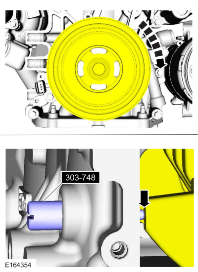
NOTE:
Only rotate the crankshaft clockwise direction.
Rotate the crankshaft slowly clockwise until the crankshaft balance
weight is up against the TDC Timing Peg. The engine is now at TDC .
-
-
-
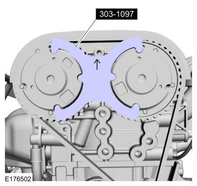
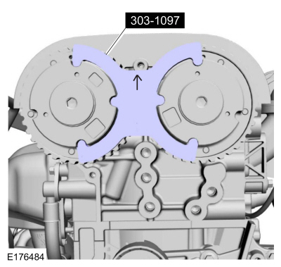
NOTE:
The timing mark of each VCT unit must be at the 12 o'clock position.
NOTE:
It may necessary to rotate the camshafts slightly to install the special tool.
Install Special Service Tool: 303-1097
Locking Tool, Variable Camshaft Timing Oil Control Unit.
-
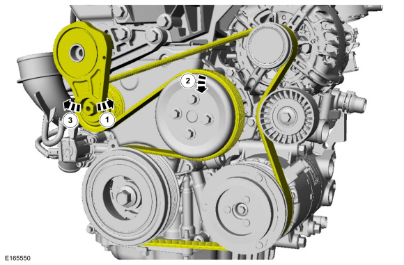
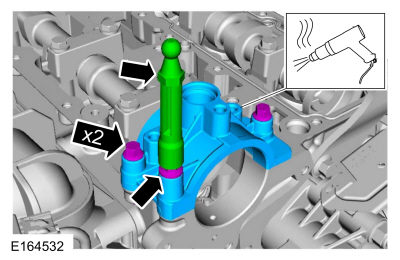
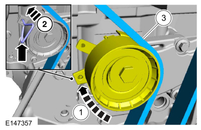
 WARNING:
The timing belt tensioner spring is under load. Extra
care must be taken at all times when handling the tensioner. Failure to
follow this instruction may result in personal injury.
WARNING:
The timing belt tensioner spring is under load. Extra
care must be taken at all times when handling the tensioner. Failure to
follow this instruction may result in personal injury.
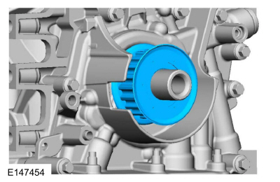
Install a holding pin.
-
-
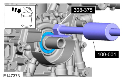
Use Special Service Tool: 308-375
Remover, Input Shaft Seal.
, 100-001
(T50T-100-A)
Slide Hammer.
-
WARNING:
The timing belt tensioner spring is under load. Extra
care must be taken at all times when handling the tensioner. Failure to
follow this instruction may result in personal injury.
-
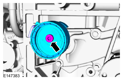
Torque:
89 lb.in (10 Nm)
-
-
Remove Special Service Tool: 303-1097
Locking Tool, Variable Camshaft Timing Oil Control Unit.
-
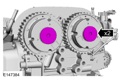
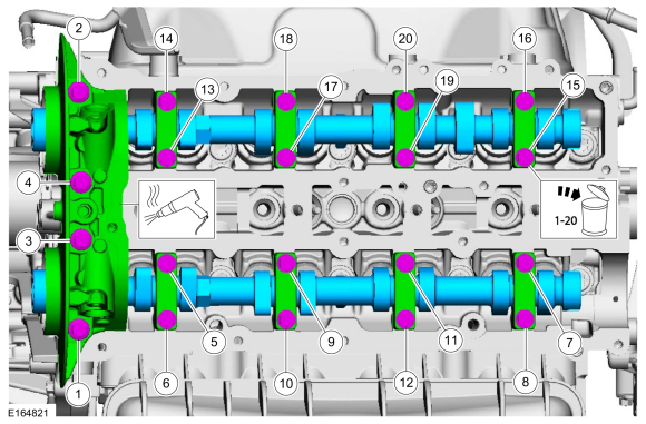
NOTE:
Use an open-ended wrench to hold the camshafts by the hexagon to prevent the camshafts from turning.
-
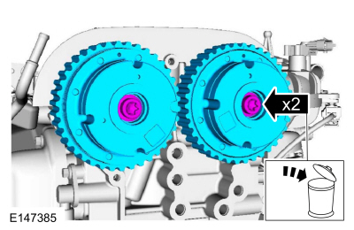
NOTE:
Use an open-ended wrench to hold the camshafts by the hexagon to prevent the camshafts from turning.
-
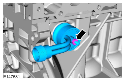
Use Special Service Tool: 303-409
(T92C-6700-CH)
Remover, Crankshaft Seal.
-
NOTICE:
Use a heat gun to soften the flange sealant, this will
aid in the removal of the camshaft mega cap. Failure to follow these
directions may result in damage to the camshaft mega cap.
NOTICE:
Do not pry on camshafts when removing or damage to the camshafts may occur.
NOTE:
Note the location and orientation of each camshaft
bearing cap and the position of the camshaft lobes on the No. 1 cylinder
for installation reference.
Use the General Equipment: Hot Air Gun
-
-
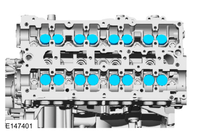
NOTE:
If the camshafts and valve tappets are to be reused,
mark the location of the valve tappets to make sure they are assembled
in their original positions.
NOTE:
The number on the valve tappets only reflects the digits
that follow the decimal. For example, a tappet with the number 0.650
has the thickness of 3.650 mm.
-
Install new components as necessary.
-
NOTE:
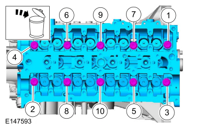
Make sure that the cylinder head is at ambient air temperature before removing the cylinder head bolts.
-
-
-
Refer to: Cylinder Head Distortion (303-00 Engine System - General Information, General Procedures).
Refer to: Cylinder Block Distortion (303-00 Engine System - General Information, General Procedures).
-
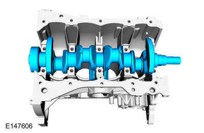
Remove Special Service Tool: 303-748
Locking Tool, Crankshaft.
-
-
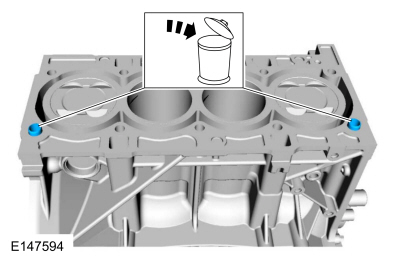
Pry pads.
-
-
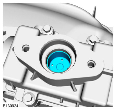
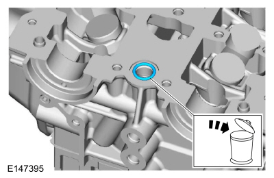
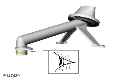
NOTE:
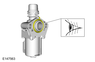
The O-ring seal is to be reused unless damaged.
-
-
-
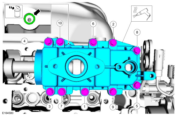
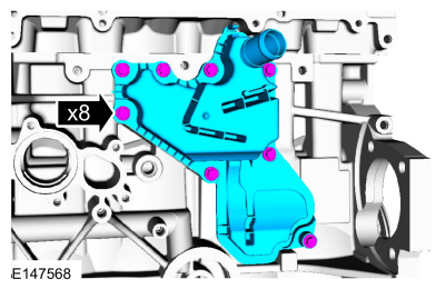
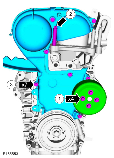
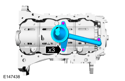
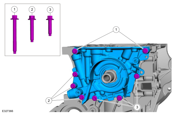
NOTE:
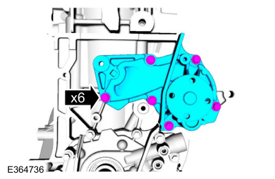
Note the position of the 3 different lengths of the bolts for installation.
-
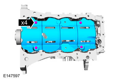
Remove the two M6 x 55 mm bolts.
-
Remove the three M6 x 35 mm bolts.
-
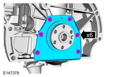
Remove the three M6 x 25 mm bolts and remove the oil pump.
-
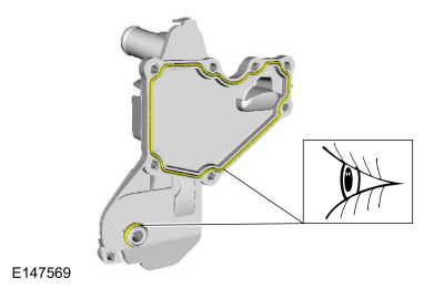
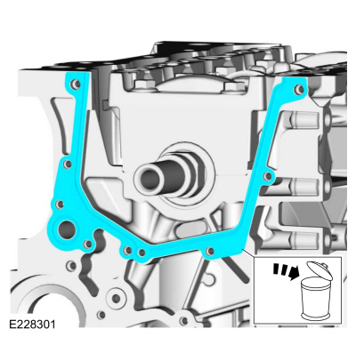
Remove and discard the oil pump gasket.
-
-
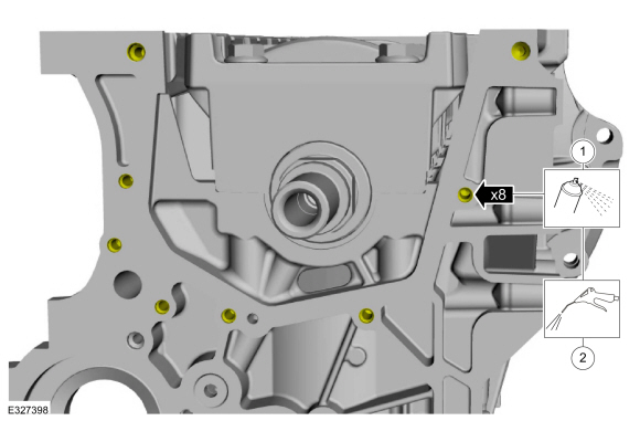
Clean the bolt holes for the oil pump with Motorcraft® Metal Brake Parts Cleaner to remove all residual oil.
Material: Motorcraft® Metal Brake Parts Cleaner
/ PM-4-A, PM-4-B, APM-4-C
-
Use compressed air to remove any brake clean or oil in the oil pump bolt holes.
-
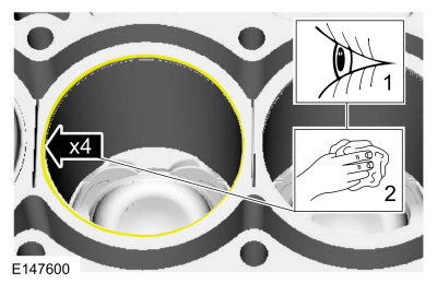
Clean the specified component with a abrasive pad.
-
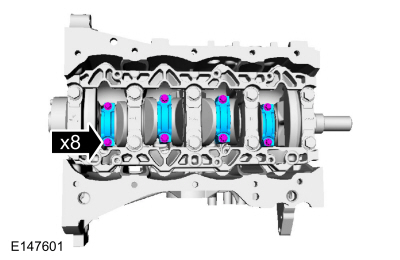
NOTE:
The connecting rod cap bolts are a torque-to-yield
design. The original connecting rod cap bolts will be used when
measuring the connecting rod large end bore during assembly. The
connecting rod cap bolts will be discarded after measurement.
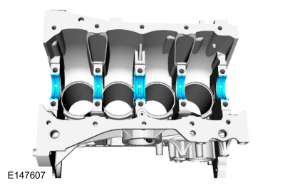
NOTE:
Clearly mark the connecting rods, connecting rod caps
and connecting rod bearings in numerical order for correct orientation
for reassembly.
-
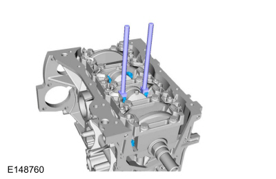
NOTE:
Do not scratch the cylinder walls or crankshaft journals with the connecting rod.
Using a connecting rod installer, repeat until all the piston/rod assemblies are removed from the engine block.
-
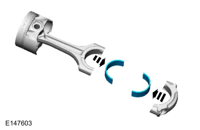
NOTE:
Mark the position of the parts, so they can be installed in their original positions.
-
Refer to: Piston Inspection (303-00 Engine System - General Information, General Procedures).
-
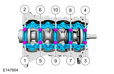
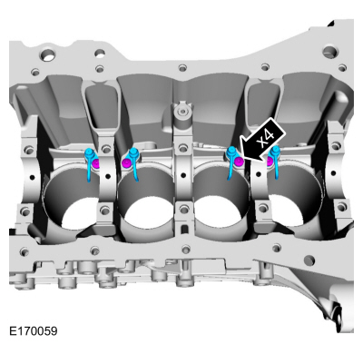
NOTE:
The main bearing beam has 2 arrows pointing towards the front of engine for correct orientation for reassembly.
-
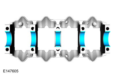
NOTE:
If the main bearings are being reused, mark them in order for correct orientation and reassembly.
-
-
NOTE:
If the main bearings are being reused, mark them in order for correct orientation and reassembly.
NOTE:
The center bulkhead has the thrust bearing.
-
Special Tool(s) /
General Equipment
303-1249Valve Spring CompressorTKIT-2006UF-FLMTKIT-2006UF-ROW
303-300
(T87C-6565-A)
Set, Valve Spring CompressorTKIT-1988-FESTIVAT88C-1000-STTKIT-1988-TRACERTKIT-2009TC-F
303-350
(T89P-6565-A)
Compressor, Valve SpringTKIT-1990-LMHTKIT-1989-FTKIT-1989-FMTKIT-1989-FLM
303-472
(T94P-6565-AH)
Adapter, Valve Sp..
Other information:
Removal
NOTICE:
Do not service the brake pedal or brake booster without
first removing the stoplamp switch and the cruise control deactivator
switch. Remove the switches with the brake pedal in the at-rest
position. The switch plunger must be compressed for the switch to rotate
in the bracket. Removing the switches with the plunger extended (during
pedal apply) will result in swit..
Removal
WARNING:
The following procedure prescribes critical repair steps
required for correct restraint system operation during a crash. Follow
all notes and steps carefully. Failure to follow step instructions may
result in incorrect operation of the restraint system and increases the
risk of serious personal injury or death in a crash.
NOTE:
RH side shown, LH ..
Categories
Special Tool(s) /
General Equipment
Flat Headed Screw Driver
Transmission Jack
Vehicle/Axle Stands
Removal
NOTICE:
Suspension fasteners are critical parts that affect
performance of vital components and systems. Failure of these fasteners
may result in major service expense. Use the same or equivalent parts if
replacement is necessary. Do not use a replacement part of lesser
quality or substitute design. Tighten fasteners as specified.
Remove the floor console.
Refer to: Floor Console (501-12 Instrum
read more

 Engine. Removal
 Cylinder Head. Disassembly and Assembly of Subassemblies