Ford Fiesta: Handles, Locks, Latches and Entry Systems / Door Latch Lubrication. General Procedures
Ford Fiesta 2014 - 2019 Service Manual / Body and Paint / Handles, Locks, Latches and Entry Systems / Door Latch Lubrication. General Procedures
Special Tool(s) / General Equipment
| Flat-Bladed Screwdriver |
Materials
| Name | Specification |
|---|---|
| Motorcraft® Multi-Purpose Grease Spray XL-5-A |
ESB-M1C93-B |
Activation
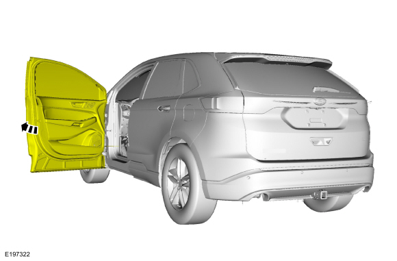
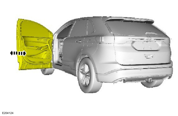
NOTE: Typical left front door shown, others similar.
-
Open the door.
 |
-
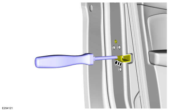
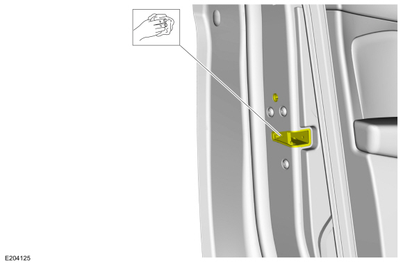
Using a flat blade screwdriver, fully close the latch (2 clicks).
Use the General Equipment: Flat-Bladed Screwdriver
 |
-
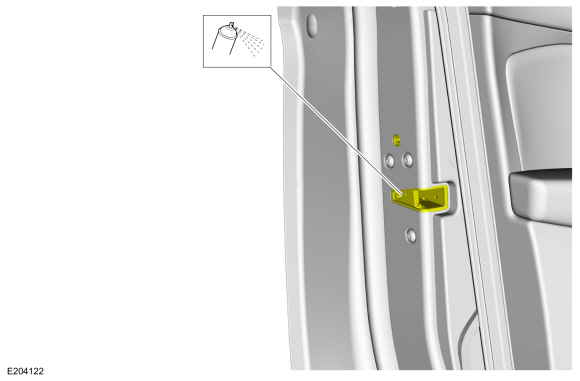
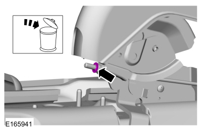
NOTICE: Do not over-lubricate the latch. Using excessive grease may damage the internal lock motor.
Spray the multi-purpose grease into the opening on the door latch for approximately 5 seconds.
Material: Motorcraft® Multi-Purpose Grease Spray / XL-5-A (ESB-M1C93-B)
 |
-
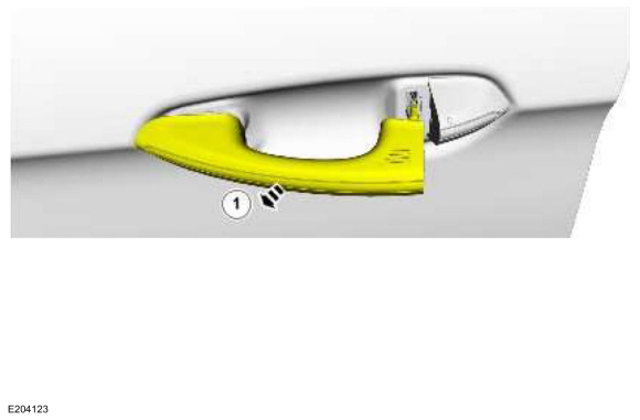
NOTE: Some exterior door handles are operated mechanically while other exterior door handles are operated electronically.
Open the latch using the exterior door handle.
 |
-
Open and close the door several times to circulate the lubricant inside the latch.
 |
-
Open the door.
|
-
Wipe off any excess grease.
 |
 Locks, Latches and Entry Systems. Diagnosis and Testing
DTC Chart: BCM
Diagnostics in this manual assume a certain skill level and knowledge of Ford-specific diagnostic practices.REFER to: Diagnostic Methods (100-00 General Information, Description and Operation)...
 Remote Keyless Entry (RKE) Transmitter Programming. General Procedures
Programming
NOTE:
All RKE transmitters must be programmed at the same time. Entering the
programming mode erases all previously programmed RKE transmitters
(Integrated Keyhead Transmitters (IKTs) and key fobs)...
Other information:
Ford Fiesta 2014 - 2019 Service Manual: Pinpoint Test - DTC: C. Diagnosis and Testing
B0004:11, B0004:12, B0004:13 and B0004:1A Refer to Wiring Diagrams Cell 46 for schematic and connector information. Normal Operation and Fault Conditions The RCM continuously monitors the driver lower airbag circuits for the following faults: Resistance out of range Unexpected voltage Short to ground Faulted driver lower airbag If..
Ford Fiesta 2014 - 2019 Service Manual: Specifications
Item Specification Roof opening panel glass clearance-front edge -0.039 – 0.00 in (-1.0 – 0.0 mm) Roof opening panel glass clearance-rear edge 0.00 – 0.039 in (0.0 – 1.0 mm) ..
Categories
- Manuals Home
- Ford Fiesta Service Manual (2014 - 2019)
- Engine Component View. Description and Operation
- Camshafts. Removal and Installation
- Manual Transmission - 6-Speed Manual Transmission – B6
- Lower Arm. Removal and Installation
- Cylinder Head. Removal and Installation
Parking Brake Control. Removal and Installation
Removal
NOTE: Removal steps in this procedure may contain installation details.
Remove the floor console.Refer to: Floor Console (501-12 Instrument Panel and Console, Removal and Installation).
Remove the driver seat.
Refer to: Front Seat (501-10 Seating, Removal and Installation).
Remove the parking brake cable adjustment lock nut.
 Loosen the parking brake cable adjustment nut.
Copyright © 2026 www.fofiesta7.com