Ford Fiesta: Engine Cooling - 1.6L EcoBoost (132kW/180PS) – Sigma / Cooling Fan Motor and Shroud. Removal and Installation
Ford Fiesta 2014 - 2019 Service Manual / Engine / Engine Cooling - 1.6L EcoBoost (132kW/180PS) – Sigma / Cooling Fan Motor and Shroud. Removal and Installation
Removal
NOTE: Removal steps in this procedure may contain installation details.
-
Remove the air cleaner.
Refer to: Air Cleaner (303-12B Intake Air Distribution and Filtering - 1.6L EcoBoost (132kW/180PS) – Sigma, Removal and Installation).
-
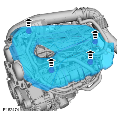
Remove the engine appearance cover.
 |
-
-
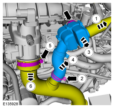
Disconnect the resonator tube.
-
Release the clamp.
-
Detach the grommet.
-
Remove the resonator assembly.
-
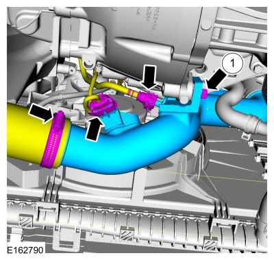
Loosen the clamp.
Torque: 44 lb.in (5 Nm)
-
Position aside the CAC outlet pipe.
-
Disconnect the resonator tube.
 |
-
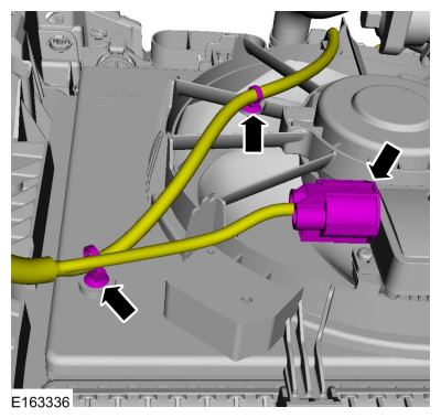
-
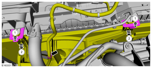
Detach the wiring harness retainer and release the tabs.
-
Position aside the cooling fan motor and shroud assembly.
-
Detach the wiring harness retainer and release the tabs.
 |
-
With the vehicle in NEUTRAL, position it on a hoist.
Refer to: Jacking and Lifting - Overview (100-02 Jacking and Lifting, Description and Operation).
-
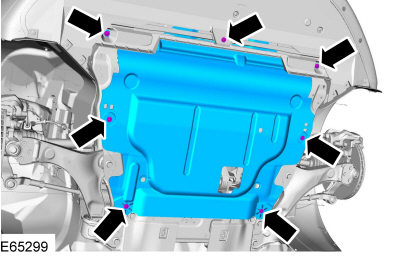
Remove the retainers and the underbody shield.
 |
-
-
Remove the bolt.
Torque: 133 lb.in (15 Nm)
-
Disconnect the electrical connector and the vent tube.
-
Loosen the clamp and remove the CAC inlet pipe.
-
Remove the bolt.
 |
-
Detach the wiring harness retainers and disconnect the electrical connector.
 |
-
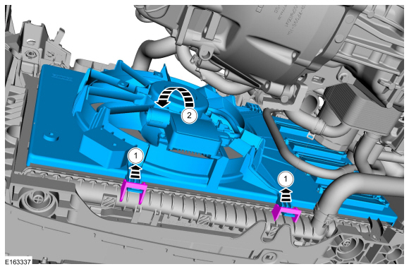
-
Release the tabs.
-
Remove the cooling fan motor and shroud.
-
Release the tabs.
 |
Installation
-
To install, reverse the removal procedure.
 Coolant Shutoff Solenoid Valve. Removal and Installation
Removal
NOTE:
Removal steps in this procedure may contain installation details.
Drain the cooling system.
Refer to: Engine Cooling System Draining, Vacuum Filling and Bleeding
(303-03B Engine Cooling - 1...
 Degas Bottle. Removal and Installation
Special Tool(s) /
General Equipment
Fluid Suction Gun
Locking Pliers
Materials
Name
Specification
Motorcraft® Orange Prediluted Antifreeze/CoolantVC-3DIL-B
WSS-M97B44-D2
Removal
NOTE:
Removal steps in this procedure may contain installation details...
Other information:
Ford Fiesta 2014 - 2019 Service Manual: Evaporator. Removal and Installation
Removal NOTE: Removal steps in this procedure may contain installation details. Remove the instrument panel. Refer to: Instrument Panel (501-12 Instrument Panel and Console, Removal and Installation). Disconnect the electrical connectors, detach the wiring harness retainers and position aside the wiring harness...
Ford Fiesta 2014 - 2019 Service Manual: Brake Caliper. Removal and Installation
Removal NOTE: Removal steps in this procedure may contain installation details. Remove the wheel and tire. Refer to: Wheel and Tire (204-04A Wheels and Tires, Removal and Installation). NOTICE: If the fluid is spilled on the paintwork, the affected area must be immediately washed down with cold water...
Categories
- Manuals Home
- Ford Fiesta Service Manual (2014 - 2019)
- Engine. Assembly
- Engine Cooling - 1.6L EcoBoost (132kW/180PS) – Sigma
- Lower Arm. Removal and Installation
- Jacking and Lifting - Overview. Description and Operation
- Valve Cover. Removal and Installation
Brake Drum. Removal and Installation
Removal
NOTE: Removal steps in this procedure may contain installation details.
 WARNING:
Before beginning any service procedure in this
manual, refer to health and safety warnings in section 100-00 General
Information. Failure to follow this instruction may result in serious
personal injury.
WARNING:
Before beginning any service procedure in this
manual, refer to health and safety warnings in section 100-00 General
Information. Failure to follow this instruction may result in serious
personal injury.
Remove the wheel and tire.
Refer to: Wheel and Tire (204-04A Wheels and Tires, Removal and Installation).
Copyright © 2026 www.fofiesta7.com