Ford Fiesta: Front Disc Brake / Brake Disc. Removal and Installation
Ford Fiesta 2014 - 2019 Service Manual / Brake System / Front Disc Brake / Brake Disc. Removal and Installation
Materials
| Name | Specification |
|---|---|
| Motorcraft® Metal Brake Parts Cleaner PM-4-A, PM-4-B, APM-4-C |
- |
Removal
NOTE: Removal steps in this procedure may contain installation details.
-
Refer to: Brake and Clutch Systems Health and Safety Precautions (100-00 General Information, Description and Operation).
-
Remove the wheels and tire.
Refer to: Wheel and Tire (204-04A Wheels and Tires, Removal and Installation).
Refer to: Brake Caliper - Detach from the wheel knuckle (206-03 Front Disc Brake, Removal and Installation).
-
Remove the brake disc.
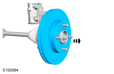 |
-
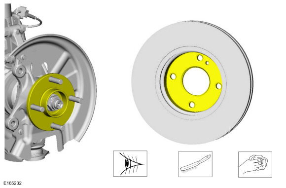
NOTE: Make sure that the mating faces are clean and free of foreign material.
Clean the brake disc-to-wheel hub mating surfaces.
Material: Motorcraft® Metal Brake Parts Cleaner / PM-4-A, PM-4-B, APM-4-C
 |
Installation
-
To install, reverse the removal procedure.
 Brake Caliper Anchor Plate. Removal and Installation
Removal
Refer to: Brake and Clutch Systems Health and Safety Precautions (100-00 General Information, Description and Operation).
Remove the brake pads...
 Brake Pads. Removal and Installation
Materials
Name
Specification
Motorcraft® DOT 4 LV High Performance Motor Vehicle Brake FluidPM-20
WSS-M6C65-A2
Removal
NOTE:
Removal steps in this procedure may contain installation details...
Other information:
Ford Fiesta 2014 - 2019 Service Manual: Pinpoint Test - DTC: Q. Diagnosis and Testing
B1405:11, B1405:12, B1405:13 and B1405:1A Refer to Wiring Diagrams Cell 46 for schematic and connector information. Normal Operation and Fault Conditions The RCM continuously monitors the LH side air curtain circuits for the following faults: Resistance out of range Unexpected voltage Short to ground Faulted LH side air curtain ..
Ford Fiesta 2014 - 2019 Service Manual: Pinpoint Test - DTC: D. Diagnosis and Testing
B0010:11, B0010:12, B0010:13 and B0010:1A Refer to Wiring Diagrams Cell 46 for schematic and connector information. Normal Operation and Fault Conditions The RCM continuously monitors the passenger airbag stage 1 circuits for the following faults: Resistance out of range Unexpected voltage Short to ground Faulted passenger airbag ..
Categories
- Manuals Home
- Ford Fiesta Service Manual (2014 - 2019)
- Engine
- Maintenance Schedules
- Engine - 1.6L EcoBoost (132kW/180PS) – Sigma
- Clutch - 6-Speed Manual Transmission – B6
- Engine. Assembly
Brake Master Cylinder. Removal and Installation
Removal
NOTICE: If the fluid is spilled on the paintwork, the affected area must be immediately washed down with cold water.
NOTE: Removal steps in this procedure may contain installation details.
All vehicles
Remove the battery tray.Refer to: Battery Tray - 1.6L Duratec-16V Ti-VCT (88kW/120PS) – Sigma (414-01 Battery, Mounting and Cables, Removal and Installation).
Refer to: Battery Tray - 1.6L EcoBoost (132kW/180PS) – Sigma (414-01 Battery, Mounting and Cables, Removal and Installation).
Disconnect the vacuum tube from the brake booster and detach the routing clip.
Copyright © 2026 www.fofiesta7.com