Ford Fiesta: Instrumentation, Message Center and Warning Chimes / Instrument Panel Cluster (IPC). Removal and Installation
Special Tool(s) / General Equipment
| Interior Trim Remover |
Removal
NOTE: Removal steps in this procedure may contain installation details.
NOTE: If installing a new IPC , all vehicle keys without push button start are erased during the parameter reset procedure. Verify at least 2 of the vehicle keys are available prior to carrying out this procedure.
NOTE: If a new IPC without push button start is installed, the IPC and the PCM require a parameter reset to allow the IPC and the PCM to recognize each other. Failure to carry out the parameter reset to the IPC and the PCM may result in a no start condition.
-
NOTE: This step is only necessary when installing a new component.
NOTE: The PMI process must begin with the current IPC installed. If the current IPC does not respond to the diagnostic scan tool, the tool may prompt for As-Built Data as part of the repair.
Using a diagnostic scan tool, begin the PMI process for the IPC following the on-screen instructions.
-
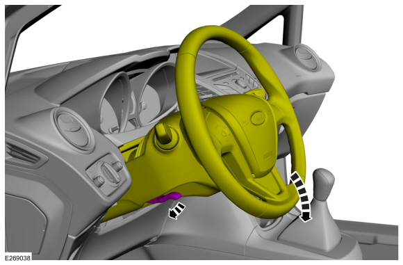
Lower the Steering Column.
 |
-
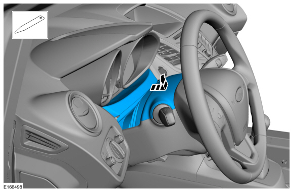
Remove the upper steering column shroud.
Use the General Equipment: Interior Trim Remover
 |
-
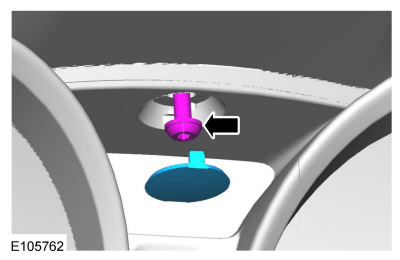
Remove the IPC center bolt cover and bolt.
 |
-
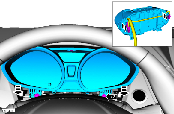
Remove the bolts and the IPC . Disconnect the electrical connectors.
Torque: 18 lb.in (2 Nm)
 |
Installation
-
To install, reverse the removal procedure.
-
NOTE: This step is only necessary when installing a new component.
NOTE: If installing a new push button start IPC remove relay R7 from the CJB and jumper pins 3 and 5 together. After configuration, remove the jumper and reinstall relay R7.
Using a diagnostic scan tool, complete the PMI process for the IPC following the on-screen instructions.
-
If installing a new IPC without push button start, carry out the parameter reset procedure.
Refer to: Passive Anti-Theft System (PATS) Parameter Reset (419-01B Passive Anti-Theft System (PATS) - Vehicles Without: Keyless Entry and Push Button Start, General Procedures).
-
If installing a new IPC without push button start, carry out the key programming procedure.
Refer to: Key Programming Using Diagnostic Equipment (419-01B Passive Anti-Theft System (PATS) - Vehicles Without: Keyless Entry and Push Button Start, General Procedures).
 Seatbelt Minder Deactivating/Activating. General Procedures
Activation
WARNING:
Before beginning any service procedure in this section,
refer to Safety Warnings in section 100-00 General Information...
 Horn
Horn
..
Other information:
Ford Fiesta 2014 - 2019 Service Manual: Pyrotechnic Device Disposal. General Procedures
Disposal Disposal of Deployable Devices and Pyrotechnic Devices That Are Undeployed-Inoperative NOTE: All inoperative airbags, seatbelt pretensioners and inflatable seatbelt inflators have been placed on the Mandatory Return List. Treat all discolored or damaged airbags the same as any inoperative live airbag being returned. WARNING: Before beginning..
Ford Fiesta 2014 - 2019 Service Manual: Parking Aid - System Operation and Component Description. Description and Operation
System Operation System Diagram Item Description 1 Video camera 2 IPC 3 TCM 4 LIN 5 Video signal 6 Infotainment Controller Area Network (I-CAN) 7 HS-CAN 8 MS-CAN 9 PCM 10 Reversing lamp switch 11 Manual transm..
Categories
- Manuals Home
- Ford Fiesta Service Manual (2014 - 2019)
- Engine
- Engine Component View. Description and Operation
- Service Information
- Engine - 1.6L EcoBoost (132kW/180PS) – Sigma
- Camshafts. Removal and Installation
Brake Drum. Removal and Installation
Removal
NOTE: Removal steps in this procedure may contain installation details.
 WARNING:
Before beginning any service procedure in this
manual, refer to health and safety warnings in section 100-00 General
Information. Failure to follow this instruction may result in serious
personal injury.
WARNING:
Before beginning any service procedure in this
manual, refer to health and safety warnings in section 100-00 General
Information. Failure to follow this instruction may result in serious
personal injury.
Remove the wheel and tire.
Refer to: Wheel and Tire (204-04A Wheels and Tires, Removal and Installation).