Ford Fiesta: Fuel Tank and Lines - 1.6L EcoBoost (132kW/180PS) – Sigma / Fuel Lines. Removal and Installation
Ford Fiesta 2014 - 2019 Service Manual / Fuel System / Fuel Tank and Lines - 1.6L EcoBoost (132kW/180PS) – Sigma / Fuel Lines. Removal and Installation
Removal
NOTE: Removal steps in this procedure may contain installation details.
-
Remove the Fuel Tank.
Refer to: Fuel Tank (310-01B Fuel Tank and Lines - 1.6L EcoBoost (132kW/180PS) – Sigma, Removal and Installation).
-
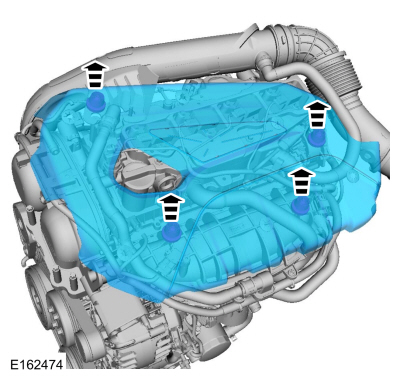
Remove the engine cover.
 |
-
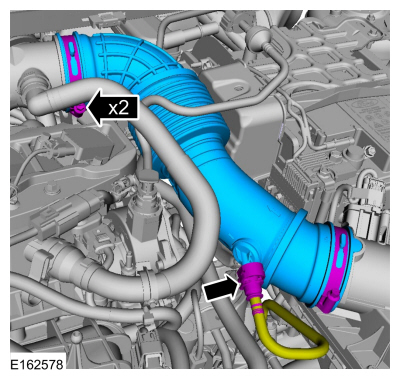
Remove the air cleaner outlet pipe.
Refer to: Air Cleaner Outlet Pipe (303-12B Intake Air Distribution and Filtering - 1.6L EcoBoost (132kW/180PS) – Sigma, Removal and Installation).
Refer to: Quick Release Coupling (310-00B Fuel System - General Information - 1.6L EcoBoost (132kW/180PS) – Sigma, General Procedures).
 |
-
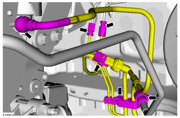
NOTE: Some residual fuel may remain in the fuel tubes after releasing the fuel system pressure. When disconnecting or removing any fuel tubes, carefully drain any residual fuel into a suitable container.
NOTE: Late build shown, early build similar.
On late build vehicles, disconnect the fuel jumper tube-to-fuel rail spring lock coupling. On early build vehicles, disconnect the quick release coupling.
Refer to: Quick Release Coupling (310-00B Fuel System - General Information - 1.6L EcoBoost (132kW/180PS) – Sigma, General Procedures).
Refer to: Spring Lock Couplings (310-00B Fuel System - General Information - 1.6L EcoBoost (132kW/180PS) – Sigma, General Procedures).
Torque: 155 lb.in (17.5 Nm)
 |
-
-
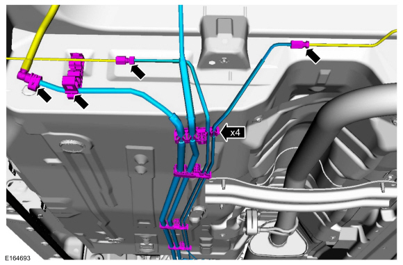
Disconnect the brake lines.
Torque: 155 lb.in (17.5 Nm)
-
Disconnect the fuel feed jumper line quick release coupling.
Refer to: Quick Release Coupling (310-00B Fuel System - General Information - 1.6L EcoBoost (132kW/180PS) – Sigma, General Procedures).
-
Release fuel line retainers and remove fuel line bundle.
-
Disconnect the brake lines.
 |
Installation
-
To install, reverse the removal procedure.
-
Bleed the brake system.
Refer to: Brake System Pressure Bleeding (206-00 Brake System - General Information, General Procedures).
 Fuel Pump and Sender Unit. Removal and Installation
Special Tool(s) /
General Equipment
310-123Locking Ring, Fuel TankTKIT-2004J-FTKIT-2005U-LM
Removal
NOTE:
Removal steps in this procedure may contain installation details...

Other information:
Ford Fiesta 2014 - 2019 Service Manual: Front Fog Lamp Adjustment. General Procedures
Adjustment NOTE: Horizontal aim is not required for this vehicle and is not adjustable. Consult your state vehicle inspection center for recommended tolerance ranges for visual aiming. Before starting the fog lamp assembly adjustment: Check the tire inflation. Make sure there are no other loads in the vehicle other than a half tank of fuel...
Ford Fiesta 2014 - 2019 Service Manual: Interior Rear View Mirror. Removal and Installation
Special Tool(s) / General Equipment 501-025Installer, Rear View Mirror 501-190Remover, Auto Dimming Rear View Mirror 501-191Installer, Rear View Mirror 501-D118A (501-D118) Mirror Remover Removal NOTE: Removal steps in this procedure may contain installation details. WARNING: Before beginning any service proc..
Categories
- Manuals Home
- Ford Fiesta Service Manual (2014 - 2019)
- Valve Cover. Removal and Installation
- Engine Component View. Description and Operation
- Engine System - General Information
- Timing Belt. Removal and Installation
- Manual Transmission - 6-Speed Manual Transmission – B6
Wheels and Tires. Diagnosis and Testing
Preliminary Inspection
Verify the customer concern by carrying out a road test on a smooth road. If any vibrations are apparent, Refer to the Symptom Chart: NVH.To maximize tire performance, inspect for signs of incorrect inflation and uneven wear, which may indicate a need for balancing, rotation or front suspension alignment.
Correct tire pressure and driving techniques have an important influence on tire life. Heavy cornering, excessively rapid acceleration and unnecessary sharp braking increase tire wear.
Correct tire pressure and driving techniques have an important influence on tire life. Heavy cornering, exce
Copyright © 2026 www.fofiesta7.com