
Ford Fiesta: Exterior Lighting / Fog Lamps. Diagnosis and Testing
DTC Chart: BCM
BCM DTC Chart
| DTC | Description | Action |
|---|---|---|
| B1046:23 | Front Fog Lamp Control Switch: Signal Stuck Low | GO to Pinpoint Test C |
| B1A78:12 | Front Fog Lamp: Circuit Short To Battery | GO to Pinpoint Test A |
| B1A78:14 | Front Fog Lamp: Circuit Short To Ground Or Open |
|
| U3000:49 | Control Module: Internal Electronic Failure |
The module has permanently disabled an
output because an excessive current draw fault (such as a short to
ground) has exceeded the limits that the BCM can withstand. The cause of
the excessive current draw MUST be corrected before a new BCM
is installed. ADDRESS all other Diagnostic Trouble Codes (DTCs) first.
After the cause of the concern is corrected, INSTALL a new BCM . REFER to: Body Control Module (BCM) (419-10 Multifunction Electronic Modules, Removal and Installation). For additional information on BCM Field Effect Transistor (FET) protection, REFER to: Module Controlled Functions - System Operation and Component Description (419-10 Multifunction Electronic Modules, Description and Operation). |
Symptom Chart(s)
Diagnostics in this manual assume a certain skill level and knowledge of Ford-specific diagnostic practices.
REFER to: Diagnostic Methods (100-00 General Information, Description and Operation).
Symptom Chart: Fog Lamps
Symptom Chart
| Condition | Possible Sources | Actions |
|---|---|---|
| A module does not respond to the diagnostic scan tool |
|
REFER to: Communications Network (418-00 Module Communications Network, Diagnosis and Testing). |
| Both front fog lamps are inoperative | Refer to the Pinpoint Test | GO to Pinpoint Test A |
| An individual front fog lamp is inoperative | Refer to the Pinpoint Test | GO to Pinpoint Test B |
| The front fog lamps are on continuously | Refer to the Pinpoint Test | GO to Pinpoint Test C |
Pinpoint Tests
Both Front Fog Lamps Are Inoperative
Refer to Wiring Diagrams Cell 86 for schematic and connector information.
Normal Operation and Fault Conditions
REFER to: Exterior Lighting - System Operation and Component Description (417-01 Exterior Lighting, Description and Operation).
DTC Fault Trigger Conditions
| DTC | Description | Fault Trigger Conditions |
|---|---|---|
| B1A78:12 | Front Fog Lamp: Circuit Short To Battery | A continuous and on-demand DTC that sets when the BCM detects a short to voltage from the front fog lamp relay control circuit. |
| B1A78:14 | Front Fog Lamp: Circuit Short To Ground Or Open | A continuous and on-demand DTC that sets when the BCM detects an open or short to voltage from the front fog lamp relay control circuit. |
| U3000:49 | Control Module: Internal Electronic Failure |
This DTC sets when the BCM
has permanently shut down the output driver. The module has
permanently disabled an output because an excessive current draw fault
(such as a short to ground) has exceeded the limits that the BCM can
withstand. CORRECT the cause of the excessive current draw before
installing a new BCM . For additional information on BCM Field Effect
Transistor (FET) protection, REFER to: Module Controlled Functions - System Operation and Component Description (419-10 Multifunction Electronic Modules, Description and Operation). |
Possible Sources
- Fuse(s)
- Wiring, terminals or connectors
- Headlamp switch
- Fog lamp relay
- BCM
Visual Inspection and Diagnostic Pre-checks
- Inspect the fog lamp bulbs and make sure they are OK.
- Inspect the BJB fuses 19 (20A) and 21 (7.5A).
- Inspect the headlamp switch for damage.
PINPOINT TEST A: BOTH FRONT FOG LAMPS ARE INOPERATIVE
| A1 CHECK THE BCM (BODY CONTROL MODULE) FOG LAMP SWITCH INPUT | ||||||||||
Does the BCM FOG_F_SW PID change from Off to On?
|
||||||||||
| A2 CHECK THE FOG LAMP SWITCH CIRCUIT FOR A SHORT TO VOLTAGE | ||||||||||
Is any voltage present?
|
||||||||||
| A3 CHECK THE FOG LAMP SWITCH CIRCUIT FOR AN OPEN | ||||||||||
Is the resistance less than 3 ohms?
|
||||||||||
| A4 CHECK FOR BCM (BODY CONTROL MODULE) DIAGNOSTIC TROUBLE CODE (DTCS) | ||||||||||
Is DTC B1A78:12 or B1A78:14 present?
|
||||||||||
| A5 CHECK THE FOG LAMP RELAY ENABLE CIRCUIT FOR A SHORT TO VOLTAGE | ||||||||||
Is any voltage present?
|
||||||||||
| A6 CHECK THE FOG LAMP RELAY ENABLE CIRCUIT FOR AN OPEN | ||||||||||
Is the resistance less than 3 ohms?
|
||||||||||
| A7 CHECK THE FOG LAMP RELAY | ||||||||||
Do the fog lamps illuminate?
|
||||||||||
| A8 CHECK THE FOG LAMP RELAY FOR VOLTAGE TO THE COIL | ||||||||||
Is the voltage greater than 11 volts?
|
||||||||||
| A9 CHECK THE FOG LAMP RELAY FOR VOLTAGE TO THE SWITCH | ||||||||||
Is the voltage greater than 11 volts?
|
||||||||||
| A10 CHECK FOR CORRECT BCM (BODY CONTROL MODULE) OPERATION | ||||||||||
Is the concern still present?
|


An Individual Front Fog Lamp Is Inoperative
Refer to Wiring Diagrams Cell 86 for schematic and connector information.
Normal Operation and Fault Conditions
REFER to: Exterior Lighting - System Operation and Component Description (417-01 Exterior Lighting, Description and Operation).
Possible Sources
- Bulb
- Wiring, terminals or connectors
Visual Inspection and Diagnostic Pre-checks
- Inspect the fog lamp bulb and make sure it is OK.
- Inspect the BJB fuses 35 (10A) and 36 (10A).
PINPOINT TEST B: AN INDIVIDUAL FRONT FOG LAMP IS INOPERATIVE
| B1 CHECK FOR VOLTAGE TO THE INOPERATIVE FOG LAMP | ||||||||||||||||
Is the voltage greater than 11 volts?
|
||||||||||||||||
| B2 CHECK FOG LAMP FUSE VOLTAGE SUPPLY CIRCUIT FOR AN OPEN | ||||||||||||||||
Is the voltage greater than 11 volts?
|
||||||||||||||||
| B3 CHECK FOG LAMP GROUND CIRCUIT FOR AN OPEN | ||||||||||||||||
Is the voltage greater than 11 volts?
|
The Front Fog Lamps Are On Continuously
Refer to Wiring Diagrams Cell 86 for schematic and connector information.
Normal Operation and Fault Conditions
REFER to: Exterior Lighting - System Operation and Component Description (417-01 Exterior Lighting, Description and Operation).
DTC Fault Trigger Conditions
| DTC | Description | Fault Trigger Conditions |
|---|---|---|
| B1046:23 | Front Fog Lamp Control Switch: Signal Stuck Low | A continuous and on-demand DTC that sets when the BCM detects the fog lamp switch circuit is grounded during the BCM self-test. |
| B1A78:14 | Front Fog Lamp: Circuit Short To Ground Or Open | A continuous and on-demand DTC that sets when the BCM detects an open or short to voltage from the front fog lamp relay control circuit. |
| U3000:49 | Control Module: Internal Electronic Failure |
This DTC sets when the BCM
has permanently shut down the output driver. The module has
permanently disabled an output because an excessive current draw fault
(such as a short to ground) has exceeded the limits that the BCM can
withstand. CORRECT the cause of the excessive current draw before
installing a new BCM . For additional information on BCM Field Effect
Transistor (FET) protection, REFER to: Module Controlled Functions - System Operation and Component Description (419-10 Multifunction Electronic Modules, Description and Operation). |
Possible Sources
- Wiring, terminals or connectors
- Headlamp switch
- Fog lamp relay
- BCM
Visual Inspection and Diagnostic Pre-checks
- Inspect the headlamp switch for damage.
PINPOINT TEST C: THE FRONT FOG LAMPS ARE ON CONTINUOUSLY
| C1 CHECK BCM (BODY CONTROL MODULE) DIAGNOSTIC TROUBLE CODES (DTCS) | ||||||||||
Is DTC B1046:23 or B1A78:14 present?
|
||||||||||
| C2 CHECK THE FOG LAMP SWITCH CIRCUIT FOR A SHORT TO GROUND | ||||||||||
Is the resistance greater than 10,000 ohms?
|
||||||||||
| C3 CHECK THE FOG LAMP RELAY ENABLE CIRCUIT FOR GROUND | ||||||||||
Is any voltage present?
|
||||||||||
| C4 CHECK THE FOG LAMP RELAY ENABLE CIRCUIT FOR A SHORT TO GROUND | ||||||||||
Is the resistance greater than 10,000 ohms?
|
||||||||||
| C5 CHECK THE FOG LAMP VOLTAGE SUPPLY CIRCUIT FOR A SHORT TO VOLTAGE | ||||||||||
Do the fog lamps continue to illuminate?
|
||||||||||
| C6 CHECK FOR CORRECT BCM (BODY CONTROL MODULE) OPERATION | ||||||||||
Is the concern still present?
|
 Exterior Lighting - System Operation and Component Description. Description and Operation
System Operation
Headlamps
System Diagram
Low Beams
The BCM
monitors the headlamp switch position by sending voltage signals on
multiple circuits to the headlamp switch...
 Headlamps. Diagnosis and Testing
DTC Chart: BCM
Diagnostics in this manual assume a certain skill level and knowledge of Ford-specific diagnostic practices. REFER to: Diagnostic Methods (100-00 General Information, Description and Operation)...
Other information:
Ford Fiesta 2014 - 2019 Service Manual: Battery Cables. Removal and Installation
Removal Negative battery cable If equipped, remove the battery monitoring sensor. Refer to: Battery Monitoring Sensor (414-01 Battery, Mounting and Cables, Removal and Installation). Remove the nut...
Ford Fiesta 2014 - 2019 Service Manual: Locked Seatbelt Retractor Releasing. General Procedures
Repair NOTE: If the seatbelt webbing does not extract from the seatbelt retractor from the stowed position, this may be due to a normal condition which happens when the seatbelt retracts at a high rate of speed. Follow these steps to release the seatbelt...
Categories
- Manuals Home
- Ford Fiesta Service Manual (2014 - 2019)
- Manual Transmission - 6-Speed Manual Transmission – B6
- Clutch - 6-Speed Manual Transmission – B6
- Lower Arm. Removal and Installation
- Engine System - General Information
- Maintenance Schedules
Parking Brake Control. Removal and Installation
Removal
NOTE: Removal steps in this procedure may contain installation details.
Remove the floor console.Refer to: Floor Console (501-12 Instrument Panel and Console, Removal and Installation).
Remove the driver seat.
Refer to: Front Seat (501-10 Seating, Removal and Installation).
Remove the parking brake cable adjustment lock nut.
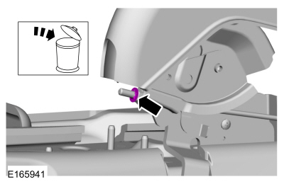 Loosen the parking brake cable adjustment nut.
